
Follow these best practices to optimize the appearance and performance of textures in your Android game.
Textures are a core element of your 3D art. 3D games that run well on the largest number of devices begin with 3D art that has been designed to best take advantage of graphics processors. This guide highlights optimizations and best practices for textures on mobile to make your game perform better and minimize power consumption while maintaining high visual quality.
Portions of this article are based on work contributed and copyrighted by Arm Limited.
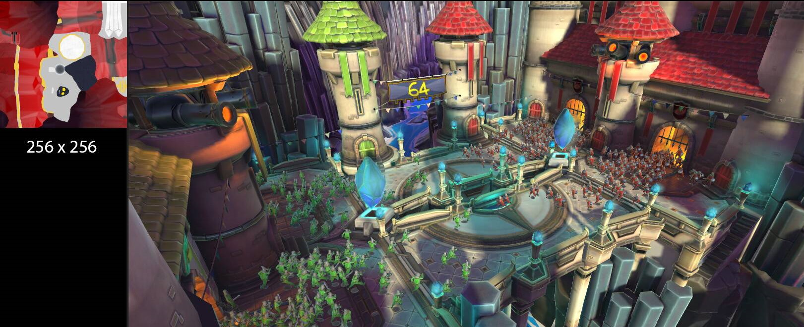
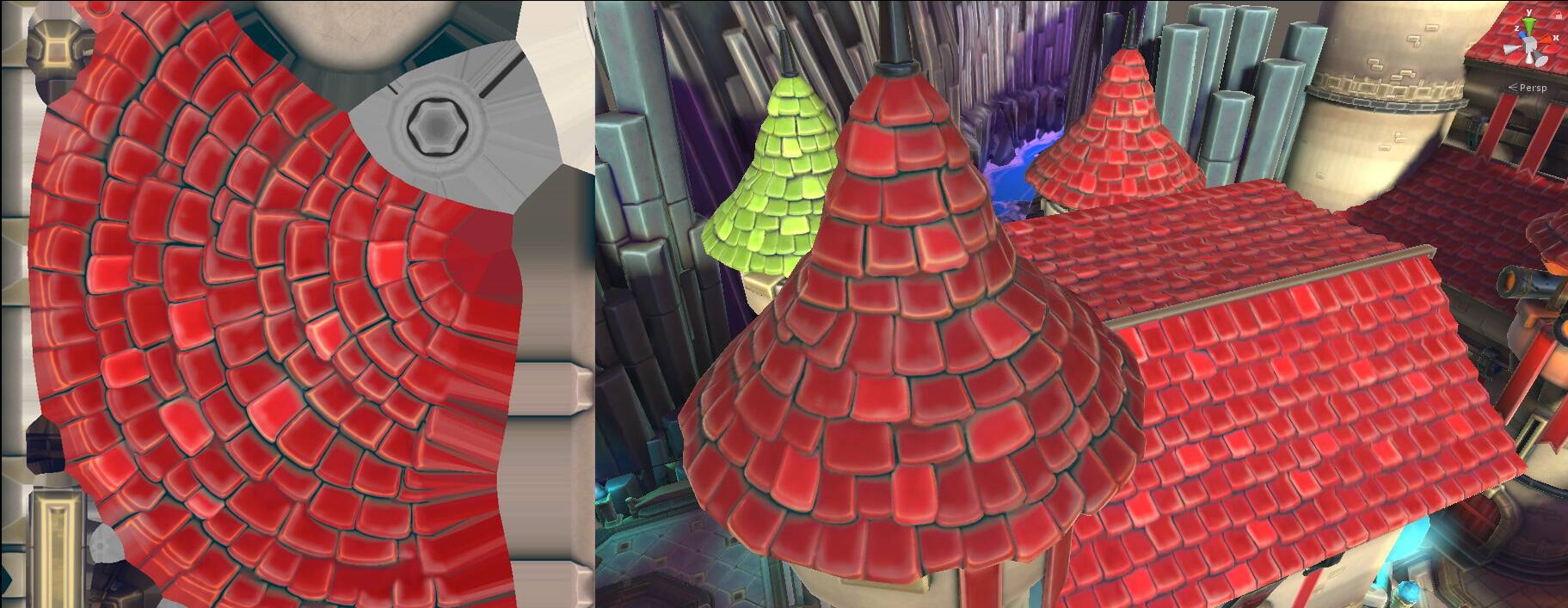
Create Texture Atlases
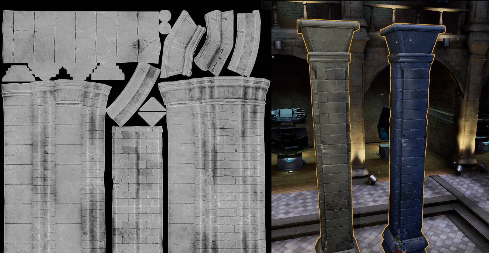
A texture atlas is a texture designed to contain the image data of multiple graphic objects, such as 3D meshes or 2D sprites. Instead of each object having its own texture, an atlas texture is used to combine the images from each object.
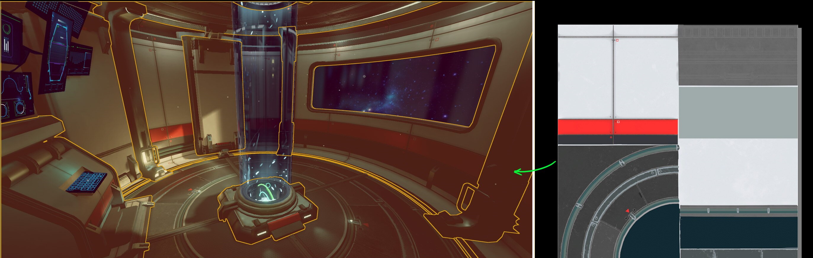
Minimizing the number of draw calls of a game frame is an important element in achieving optimal rendering performance. Using the same texture for different objects is one factor for combining them into a single draw call. Reducing draw calls is particularly important for games that are CPU bound, as each draw call incurs CPU overhead as it is processed by the graphics driver. Texture atlases also reduce the number of texture asset files in the runtime data of your game. Hundreds or even thousands of textures can be consolidated into a much smaller number of texture atlas files.
You should plan your texture atlas layout when creating 3D meshes. If the atlas is authored before making the mesh asset, the mesh asset must be UV unwrapped following the texture atlas. If the atlas is created after authoring, using merging or atlas creation tools in painting software, the UV island will need to be rearranged according to the texture.
Engine specific draw call batching
The Unity game engine has a draw call batching feature that can automatically combine objects. To be eligible for automatic batching, objects must share a common material, including textures, and be marked static.
Unreal Engine 4 requires manual setup for batching. You can merge objects in 3D software before importing them into Unreal. Unreal also includes the UE4 Actor Merging tool which can combine meshes and create texture atlas files.
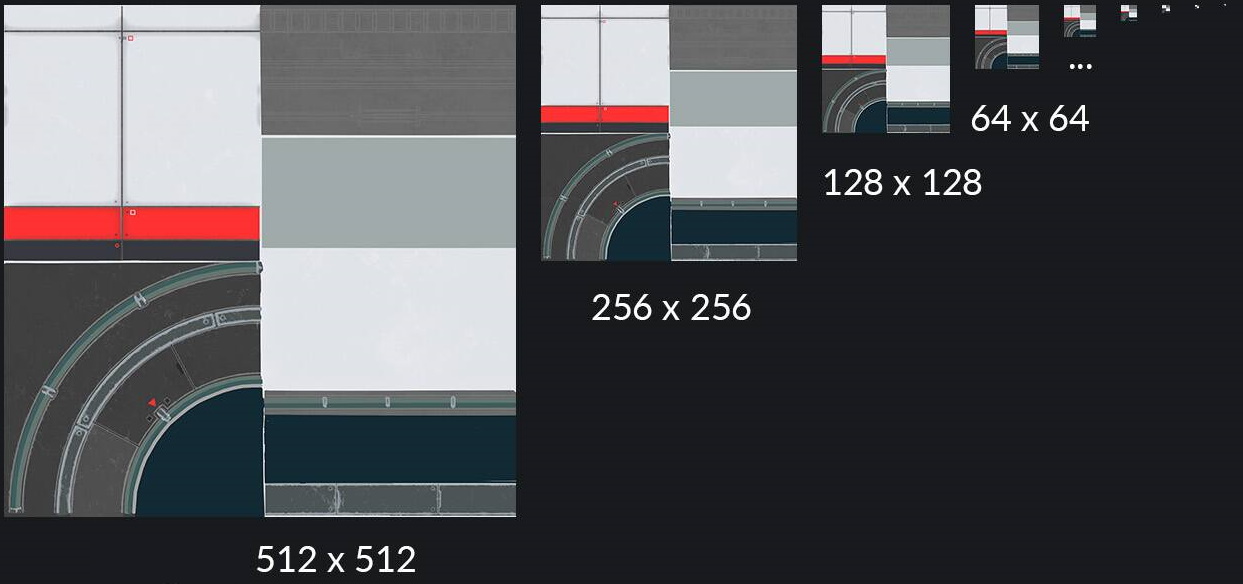
Generate Mipmaps
Mipmaps are lower resolution versions of a texture. A collection of mipmaps for a given texture is called a mipmap chain. Each subsequent mipmap level in a chain is a lower resolution than the preceding level. Mipmaps are used to implement texture LOD (level of detail) during rendering. When a mipmapped texture is bound to a texture stage, the graphics hardware uses the texture space occupied by a fragment to choose a level from the mipmap chain. When rendering a 3D scene, an object further away from the camera will use a lower resolution mipmap than the same object closer to the camera.
A mipmapped texture uses more memory compared to a non mipmapped texture. The additional mipmap levels increase the memory footprint of a texture by 33%. If a texture is drawn at a fixed distance from the camera, generating mipmaps is an unnecessary use of memory.
Correctly using mipmaps improves GPU performance. Availability of lower resolution mipmap levels reduces memory bandwidth usage and improves texture cache residency.
Mipmapping can also improve visual quality by reducing texture aliasing. Texture aliasing can be observed as a flickering effect on areas further from the camera.
Engine specific mipmap details
Unreal Engine 4 requires texture dimensions that are powers of two (e.g. 512x1024, 128x128) to use mipmapping. Mipmap chains will not be generated if one or both texture dimensions is not a power of two.
The Unity engine will automatically scale textures with dimensions that are not a power of two to create mipmaps. Ensure your source texture files are power of two dimensions to avoid this scaling.
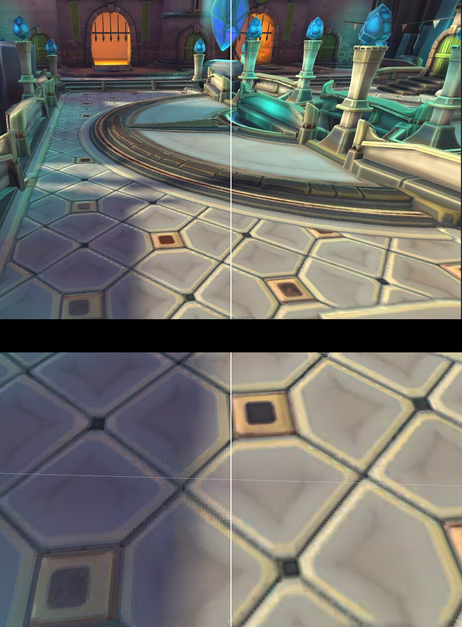
Select appropriate texture filtering modes
Texture filtering is a hardware rendering feature that affects the visual appearance of a rendered triangle. Proper use of texture filtering can improve the visual quality of a scene. There are multiple texture filtering modes, each with a different balance between rendering improvement and cost. Cost includes both computation time and memory bandwidth. Three commonly available texture filtering modes are: nearest (or point), bilinear, and trilinear. Anisotropic is an additional texture filtering method that can be combined with bilinear or trilinear filtering.
Nearest
Nearest is the simplest and least expensive texture filtering mode. Nearest samples a single texel using the specified coordinates in the source texture. Triangles rendered with nearest will have a blocky or pixelated appearance, especially when rendered close to the camera.
Bilinear
Bilinear filtering samples the four texels surrounding the specified coordinates in the source texture. These four texels are averaged to determine the texture color for the fragment. Bilinear filtering results in a smoother gradient between pixels, avoiding the blocky appearance of nearest filtering. Triangles rendered close to the camera will appear blurry instead of pixelated. Bilinear costs more than nearest due to the additional texel samples and averaging.
Trilinear
When you render a mesh where the distance of the vertices from the camera varies, multiple mipmap levels may be selected during rendering. The changes between two mipmap levels may lead to a noticeable sharp cut at the transition point. Trilinear filtering softens these transitions by performing bilinear filtering on two different mipmap levels and interpolating the results. The use of multiple mip levels and interpolation make trilinear more computationally expensive than bilinear.
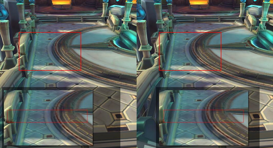
Anisotropic
Anisotropic filtering increases the visual quality of textured meshes that are rendered at an extreme angle relative to the camera. A ground plane is a common example of this kind of mesh. Anisotropic filtering requires mipmapped textures to function. The ratio or level of anisotropic filtering applied during rendering can be configured. The cost of anisotropic filtering increases as the level increases.
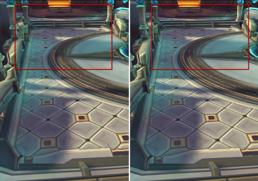
Mode selection strategy
Bilinear filtering is generally the best balance between performance and visual quality. Trilinear filtering requires significantly more memory bandwidth and should be used selectively. In many cases, bilinear filtering combined with 2x anisotropic filtering will look and perform better than trilinear filtering with 1x anisotropic filtering. Increasing anisotropic levels beyond 2x is extremely costly and should be done very selectively for critical game assets.
Texture filtering may account for up to half of the total GPU energy consumption, choosing simpler texture filters where possible is an excellent way to reduce your game’s power demands.
Optimize texture sizes
Ensure your texture dimensions are as small as possible while still achieving your desired image quality. Review your texture assets to check for erroneously large textures. This principle applies to both discrete and atlas textures. If your game supports many devices encompassing a wide range of resolution and performance capabilities, consider creating low and high resolution versions of your texture assets for the appropriate device class.
When rendering a mesh that uses multiple textures in its material, consider selectively reducing the resolution of some textures. For example, when using a diffuse texture of 1024x1024, reducing the roughness or metallic map texture to 512x512 may be possible with only a minimal impact on image quality. Verify the impact of all such resizing experiments to ensure they do not compromise the desired quality level.
Use the appropriate color space
Many software packages used for texture authoring operate in and export using the sRGB color space. Diffuse textures, which are processed as color, may use sRGB color space. Textures which are not processed as color, such as metallic, roughness, or normal maps, should not be exported in sRGB color space.
Game engine texture settings include a parameter for whether a texture uses sRGB color space.
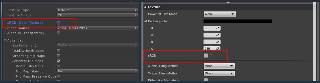
Since the pixel data of such textures is not used as color data, using the sRGB color space will produce incorrect visuals.
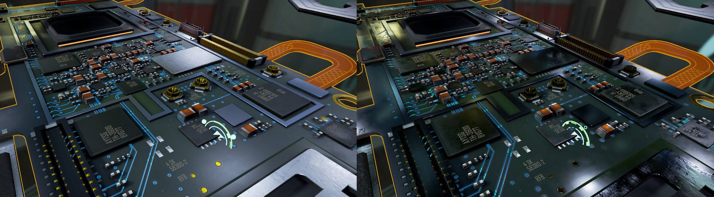
Use texture compression
Texture compression is an image compression algorithm applied to uncompressed pixel data that results in a texture that can be quickly decompressed by graphics hardware during rendering. Effective use of texture compression can reduce memory usage and increase performance with minimal impact to visual quality. Three texture compression algorithms are most common on Android: ETC1, ETC2 and ASTC. For modern games, ASTC is generally the best primary option, with ETC2 being a fallback option if your game targets devices which do not support ASTC.
ETC1
ETC1 is supported by all Android devices. ETC1 only supports a single four bit per pixel mode of RGB color data. ETC1 does not support alpha channels. Many game engines that support ETC1 allow designation of a second ETC1 texture to be used to represent alpha channel data.
ETC2
ETC2 is supported by over 90% of active Android devices. Very old devices which do not support the OpenGL ES 3.0 API are unable to use ETC2. Compared to ETC1, ETC2 adds:
- Alpha channel support, both eight bit and single bit ‘punchthrough’
- sRGB versions of RGB and RGBA textures
- One and two channel, R11 and RG11, textures
ASTC
ASTC is supported by over 75% of active Android devices. ASTC has configurable compression block sizes, which gives you fine-grained control to balance compression ratio against image quality for a given texture. ASTC is often capable of achieving superior quality at the same memory size as ETC2, or similar quantity at a smaller memory size than ETC2.
Texture compression speed
Texture compression can take a long time if your game has a lot of textures. Both ETC and ASTC have selectable compression quality settings. Higher quality settings require more time to compress. During development you may want to decrease the quality level to decrease compression time and increase the quality level before creating important builds.
Texture compression in game engines
If you are using a game engine, you may have to choose your texture compression format (ETC or ASTC) at a project level. To support multiple compression formats for maximum compatibility, additional work may be required. The Texture Compression Format Targeting feature of Google Play Asset Delivery can assist in including multiple formats in your game, and only delivering the most optimal format to an individual device at install time.
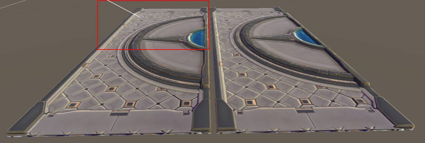
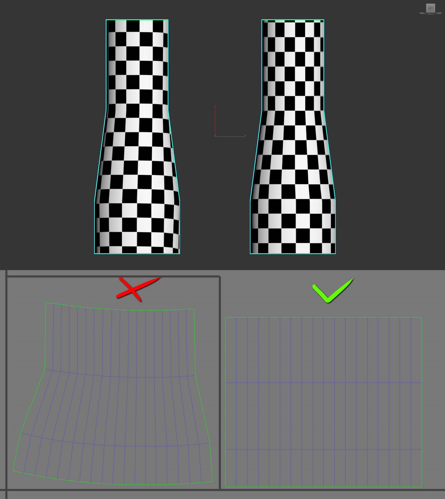
Unwrap UVs
Keep the UV island as straight as possible. This helps your texture in the following ways:
- Packing UV islands is easier, leading to less wasted space.
- Straight UVs reduce the ‘staircase effect’ on textures.
- Good UV packing ensures getting optimal resolution from the texture.
- Better quality texturing, even if UVs are slightly distorted from straightening.
Visible texture seams on a model look bad. Try to place any UV seams in places where they are less visible. To help create better normal maps, split your UV island where the edges are sharp and leave some space around the island.
Avoid imperceptible detail
When creating art, don’t add details that won’t be seen, especially on games designed for devices with smaller screens. Making an intricately detailed 4096x4096 texture is wasted on a small chair model that is barely visible in the corner of a room. In certain cases, you may need to exaggerate edges (adding extra highlights) and shading to improve shape perception.
Bake details
Mobile devices have smaller screens and less powerful graphics hardware than personal computers or gaming consoles. Instead of calculating effects like ambient occlusion or specular highlighting at runtime, consider ‘baking’ them into the diffuse texture when possible. This helps performance and ensures visibility of your details.
Use color tinting
If you have the ability to create custom shaders, and have meshes that have a similar or uniform color scheme, consider using color tinting on applicable meshes. With color tinting, a grayscale texture is used, which takes less texture memory than an RGB texture. Per vertex color data is applied by the shader to colorize the mesh. An alternative tinting method is to use an RGB mask and apply the texture based on the color range of the mask.
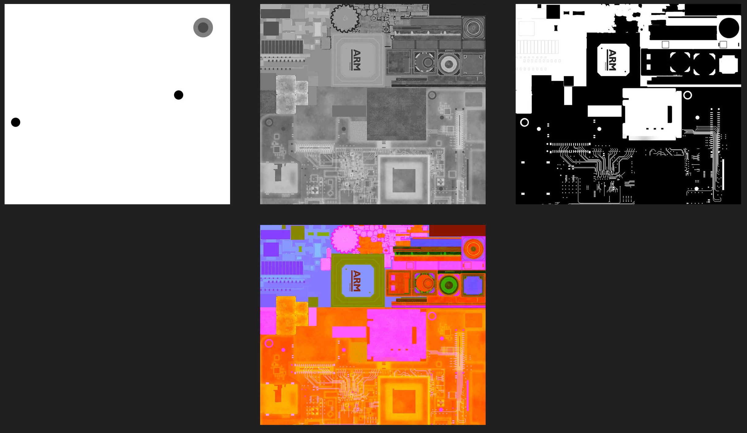
Pack texture channels
When rendering materials with multiple textures, look for opportunities to combine textures that only use a single color channel into a single texture that uses all three color channels. This reduces memory usage and decreases the number of texture sampler operations performed by the fragment shader.
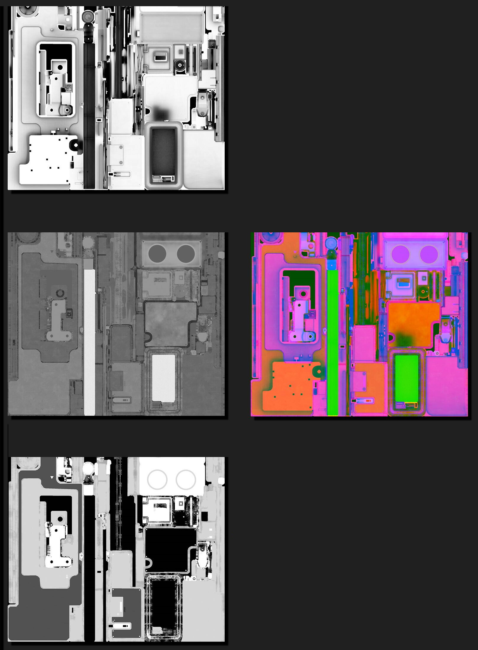
When packing, assign data with the most detail to the green channel. Since the human eye is more sensitive to green, graphics hardware usually assigns more bits to the green channel. For example, a roughness/smoothness map will usually have more detail than a metallic map, and is a better choice to assign to the green channel.
For materials that use an alpha channel, if you are only using two channels in your packed texture, consider putting the alpha channel data into your packed texture instead of your diffuse texture. Depending on the format of your diffuse texture, this can help you reduce its size, or increase its visual quality by omitting the alpha channel data.
Make sure that your packed textures are set to a linear RGB color space and not sRGB.
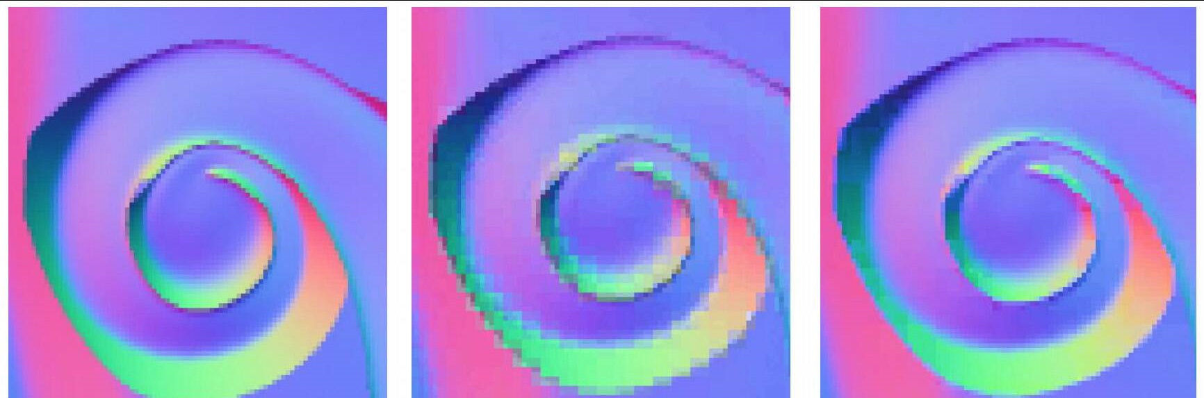
Create normal maps
Normal mapping is a technique that gives a 3D model the appearance of detail without using additional geometry. Features such as wrinkles or bolts that might require many triangles to model can be simulated using a normal map. Normal mapping may or may not be appropriate depending on the art style and direction of the game.
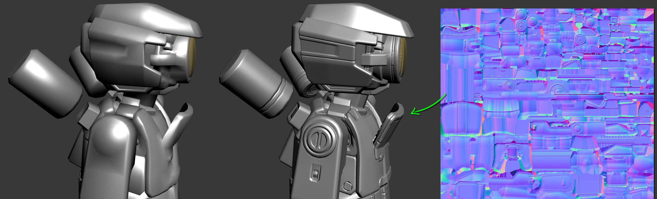
Normal maps do incur some performance cost and should be used sparingly on lower end devices. The normal map requires an additional texture, resulting in additional texture sampling and fragment shader calculations.
Normal map best practices
The following are some best practices for normal map creation:
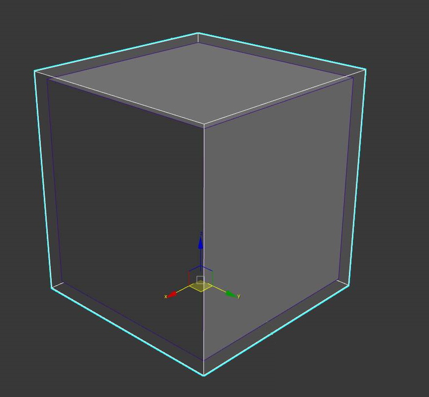
Use a cage
A cage is a larger, or pushed out, version of your low polygon model. It needs to encompass the high polygon model to work well during normal map baking. The cage is used to limit raycast distance during normal map baking and helps avoid problems with split normal seams on the normal map.
Bake matching by mesh name
If your baking software supports it, bake matching by mesh name. This feature mitigates the problem of wrong normal map projection. When objects are too close to each other, they may unexpectedly project their normal map on the wrong face. Matching by mesh name ensures the baking is only done on the correct surface. For more information on this feature in Substance Painter, see this page. Formore information on this feature in Marmoset Toolbag, see this page.
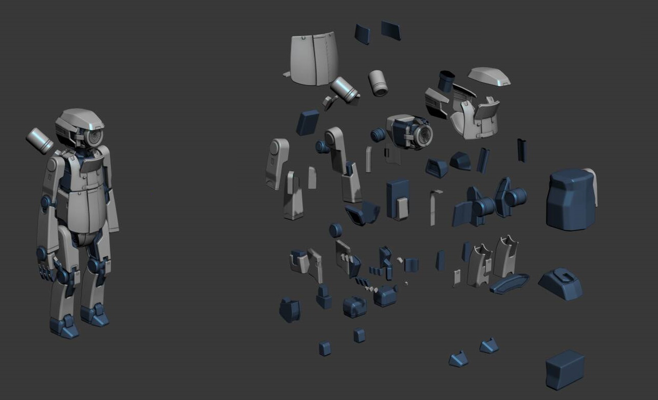
Explode the mesh
If you are unable to match by mesh name when baking, consider exploding your mesh. Exploding your mesh moves parts away from each other so that the normal map doesn’t project onto the wrong surface. If you are also baking for ambient occlusion, you may need to perform that bake separately with an unexploded mesh.
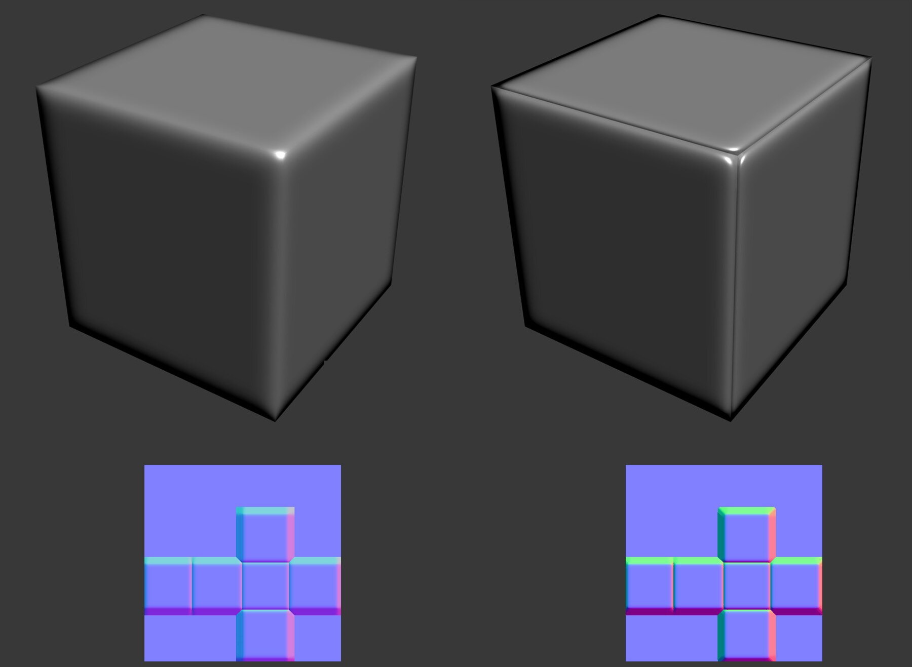
Minimize seams
Continuous UV on hard edges will cause visible seams, split UV on hard edges to minimize this effect. When setting smoothing groups, as a rule of thumb keep the angle less than 90 degrees. UV seams need to have a different smoothing group on the triangles.