投影とカメラビューを適用する
コレクションでコンテンツを整理
必要に応じて、コンテンツの保存と分類を行います。
OpenGL ES 環境では、投影とカメラビューを使用して、描画されたオブジェクトを
目で見る物理物によく似ていますこのシミュレーションは、
実際の表示は、描画されたオブジェクト座標を数学的に変換して行います。
- 投影 - この変換は、描画されたオブジェクトの座標を
それらが表示される
GLSurfaceView
の幅と高さ。なし
この計算では、OpenGL ES によって描画されたオブジェクトはビューの不均等な比率によって歪められます。
クリックします。射影変換は、通常、予測入力の比率が
OpenGL ビューは、レンダラの onSurfaceChanged()
メソッドで確立または変更します。OpenGL ES のプロジェクションと
座標マッピングについては、
描画用の座標のマッピング
オブジェクト。
- カメラビュー - この変換では、
指定します。OpenGL ES では実際のカメラは定義されないことに注意してください。
代わりに、画像の表示を変換してカメラをシミュレートするユーティリティ メソッドが提供されています。
描画されます。カメラビューの変換は、確立したときに一度しか計算されないことがあります。
GLSurfaceView
するか、ユーザーの操作や
必要があります。
このレッスンでは、投影とカメラビューを作成し、描画した図形に適用する方法について説明します。
GLSurfaceView
。
プロジェクションを定義する
射影変換のデータは onSurfaceChanged()
で計算されます
GLSurfaceView.Renderer
クラスのメソッドを呼び出します。次のサンプルコード
GLSurfaceView
の高さと幅を受け取り、それを使用して
Matrix.frustumM()
メソッドを使用して射影変換 Matrix
を使用する:
Kotlin
// vPMatrix is an abbreviation for "Model View Projection Matrix"
private val vPMatrix = FloatArray(16)
private val projectionMatrix = FloatArray(16)
private val viewMatrix = FloatArray(16)
override fun onSurfaceChanged(unused: GL10, width: Int, height: Int) {
GLES20.glViewport(0, 0, width, height)
val ratio: Float = width.toFloat() / height.toFloat()
// this projection matrix is applied to object coordinates
// in the onDrawFrame() method
Matrix.frustumM(projectionMatrix, 0, -ratio, ratio, -1f, 1f, 3f, 7f)
}
Java
// vPMatrix is an abbreviation for "Model View Projection Matrix"
private final float[] vPMatrix = new float[16];
private final float[] projectionMatrix = new float[16];
private final float[] viewMatrix = new float[16];
@Override
public void onSurfaceChanged(GL10 unused, int width, int height) {
GLES20.glViewport(0, 0, width, height);
float ratio = (float) width / height;
// this projection matrix is applied to object coordinates
// in the onDrawFrame() method
Matrix.frustumM(projectionMatrix, 0, -ratio, ratio, -1, 1, 3, 7);
}
このコードでは、射影行列 mProjectionMatrix
が入力されています。この行列は、
onDrawFrame()
メソッドでカメラビュー変換を使用します。これについては次のセクションで説明します。
注: モデルに射影変換を適用するだけで、
描画オブジェクトは通常、非常に空白の画面になります。一般的には、カメラにカメラを
ビュー変換が必要です
カメラビューの定義
カメラビュー変換を追加して、描画オブジェクトの変換プロセスを完了します。
レンダリング処理の一部にすぎません次のサンプルコードでは、カメラビューが
Matrix.setLookAtM()
を使用して計算されます。
以前に計算した射影行列と結合します。組み合わせた
変換行列が描画されたシェイプに渡されます。
Kotlin
override fun onDrawFrame(unused: GL10) {
...
// Set the camera position (View matrix)
Matrix.setLookAtM(viewMatrix, 0, 0f, 0f, 3f, 0f, 0f, 0f, 0f, 1.0f, 0.0f)
// Calculate the projection and view transformation
Matrix.multiplyMM(vPMatrix, 0, projectionMatrix, 0, viewMatrix, 0)
// Draw shape
triangle.draw(vPMatrix)
Java
@Override
public void onDrawFrame(GL10 unused) {
...
// Set the camera position (View matrix)
Matrix.setLookAtM(viewMatrix, 0, 0, 0, 3, 0f, 0f, 0f, 0f, 1.0f, 0.0f);
// Calculate the projection and view transformation
Matrix.multiplyMM(vPMatrix, 0, projectionMatrix, 0, viewMatrix, 0);
// Draw shape
triangle.draw(vPMatrix);
}
図に示す投影とカメラビュー変換行列を使用するには、
セクションをプレビューします。まず、事前に定義した頂点シェーダーにマトリックス変数を追加します。
Triangle
クラス内:
Kotlin
class Triangle {
private val vertexShaderCode =
// This matrix member variable provides a hook to manipulate
// the coordinates of the objects that use this vertex shader
"uniform mat4 uMVPMatrix;" +
"attribute vec4 vPosition;" +
"void main() {" +
// the matrix must be included as a modifier of gl_Position
// Note that the uMVPMatrix factor *must be first* in order
// for the matrix multiplication product to be correct.
" gl_Position = uMVPMatrix * vPosition;" +
"}"
// Use to access and set the view transformation
private var vPMatrixHandle: Int = 0
...
}
Java
public class Triangle {
private final String vertexShaderCode =
// This matrix member variable provides a hook to manipulate
// the coordinates of the objects that use this vertex shader
"uniform mat4 uMVPMatrix;" +
"attribute vec4 vPosition;" +
"void main() {" +
// the matrix must be included as a modifier of gl_Position
// Note that the uMVPMatrix factor *must be first* in order
// for the matrix multiplication product to be correct.
" gl_Position = uMVPMatrix * vPosition;" +
"}";
// Use to access and set the view transformation
private int vPMatrixHandle;
...
}
次に、グラフィック オブジェクトの draw()
メソッドを変更して、結合された
変換行列を作成し、それをシェイプに適用します。
Kotlin
fun draw(mvpMatrix: FloatArray) { // pass in the calculated transformation matrix
...
// get handle to shape's transformation matrix
vPMatrixHandle = GLES20.glGetUniformLocation(mProgram, "uMVPMatrix")
// Pass the projection and view transformation to the shader
GLES20.glUniformMatrix4fv(vPMatrixHandle, 1, false, mvpMatrix, 0)
// Draw the triangle
GLES20.glDrawArrays(GLES20.GL_TRIANGLES, 0, vertexCount)
// Disable vertex array
GLES20.glDisableVertexAttribArray(positionHandle)
}
Java
public void draw(float[] mvpMatrix) { // pass in the calculated transformation matrix
...
// get handle to shape's transformation matrix
vPMatrixHandle = GLES20.glGetUniformLocation(mProgram, "uMVPMatrix");
// Pass the projection and view transformation to the shader
GLES20.glUniformMatrix4fv(vPMatrixHandle, 1, false, mvpMatrix, 0);
// Draw the triangle
GLES20.glDrawArrays(GLES20.GL_TRIANGLES, 0, vertexCount);
// Disable vertex array
GLES20.glDisableVertexAttribArray(positionHandle);
}
投影とカメラビューの変換を正しく計算して適用したら、
グラフィック オブジェクトが正しい比率で描画され、次のようになります。
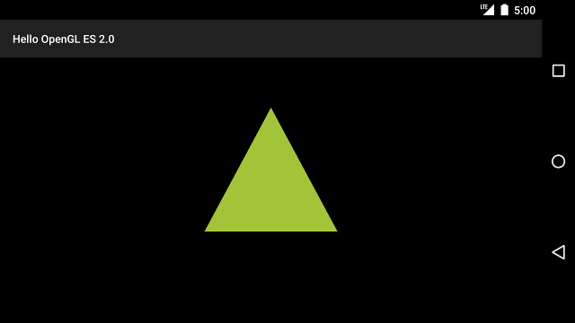
図 1. 投影とカメラビューが適用された三角形の描画。
シェイプを正しい比率で表示するアプリケーションを作成したら、次は
シェイプに動きを加えることができます。
このページのコンテンツやコードサンプルは、コンテンツ ライセンスに記載のライセンスに従います。Java および OpenJDK は Oracle および関連会社の商標または登録商標です。
最終更新日 2025-07-27 UTC。
[[["わかりやすい","easyToUnderstand","thumb-up"],["問題の解決に役立った","solvedMyProblem","thumb-up"],["その他","otherUp","thumb-up"]],[["必要な情報がない","missingTheInformationINeed","thumb-down"],["複雑すぎる / 手順が多すぎる","tooComplicatedTooManySteps","thumb-down"],["最新ではない","outOfDate","thumb-down"],["翻訳に関する問題","translationIssue","thumb-down"],["サンプル / コードに問題がある","samplesCodeIssue","thumb-down"],["その他","otherDown","thumb-down"]],["最終更新日 2025-07-27 UTC。"],[],[],null,["# Apply projection and camera views\n\nIn the OpenGL ES environment, projection and camera views allow you to display drawn objects in a\nway that more closely resembles how you see physical objects with your eyes. This simulation of\nphysical viewing is done with mathematical transformations of drawn object coordinates:\n\n- *Projection* - This transformation adjusts the coordinates of drawn objects based on the width and height of the [GLSurfaceView](/reference/android/opengl/GLSurfaceView) where they are displayed. Without this calculation, objects drawn by OpenGL ES are skewed by the unequal proportions of the view window. A projection transformation typically only has to be calculated when the proportions of the OpenGL view are established or changed in the [onSurfaceChanged()](/reference/android/opengl/GLSurfaceView.Renderer#onSurfaceChanged(javax.microedition.khronos.opengles.GL10, int, int)) method of your renderer. For more information about OpenGL ES projections and coordinate mapping, see [Mapping coordinates for drawn\n objects](/develop/ui/views/graphics/opengl/about-opengl#coordinate-mapping).\n- *Camera View* - This transformation adjusts the coordinates of drawn objects based on a virtual camera position. It's important to note that OpenGL ES does not define an actual camera object, but instead provides utility methods that simulate a camera by transforming the display of drawn objects. A camera view transformation might be calculated only once when you establish your [GLSurfaceView](/reference/android/opengl/GLSurfaceView), or might change dynamically based on user actions or your application's function.\n\nThis lesson describes how to create a projection and camera view and apply it to shapes drawn in\nyour [GLSurfaceView](/reference/android/opengl/GLSurfaceView).\n\nDefine a projection\n-------------------\n\nThe data for a projection transformation is calculated in the [onSurfaceChanged()](/reference/android/opengl/GLSurfaceView.Renderer#onSurfaceChanged(javax.microedition.khronos.opengles.GL10, int, int))\nmethod of your [GLSurfaceView.Renderer](/reference/android/opengl/GLSurfaceView.Renderer) class. The following example code\ntakes the height and width of the [GLSurfaceView](/reference/android/opengl/GLSurfaceView) and uses it to populate a\nprojection transformation [Matrix](/reference/android/opengl/Matrix) using the [Matrix.frustumM()](/reference/android/opengl/Matrix#frustumM(float[], int, float, float, float, float, float, float)) method: \n\n### Kotlin\n\n```kotlin\n// vPMatrix is an abbreviation for \"Model View Projection Matrix\"\nprivate val vPMatrix = FloatArray(16)\nprivate val projectionMatrix = FloatArray(16)\nprivate val viewMatrix = FloatArray(16)\n\noverride fun onSurfaceChanged(unused: GL10, width: Int, height: Int) {\n GLES20.glViewport(0, 0, width, height)\n\n val ratio: Float = width.toFloat() / height.toFloat()\n\n // this projection matrix is applied to object coordinates\n // in the onDrawFrame() method\n Matrix.frustumM(projectionMatrix, 0, -ratio, ratio, -1f, 1f, 3f, 7f)\n}\n```\n\n### Java\n\n```java\n// vPMatrix is an abbreviation for \"Model View Projection Matrix\"\nprivate final float[] vPMatrix = new float[16];\nprivate final float[] projectionMatrix = new float[16];\nprivate final float[] viewMatrix = new float[16];\n\n@Override\npublic void onSurfaceChanged(GL10 unused, int width, int height) {\n GLES20.glViewport(0, 0, width, height);\n\n float ratio = (float) width / height;\n\n // this projection matrix is applied to object coordinates\n // in the onDrawFrame() method\n Matrix.frustumM(projectionMatrix, 0, -ratio, ratio, -1, 1, 3, 7);\n}\n```\n\nThis code populates a projection matrix, `mProjectionMatrix` which you can then combine\nwith a camera view transformation in the [onDrawFrame()](/reference/android/opengl/GLSurfaceView.Renderer#onDrawFrame(javax.microedition.khronos.opengles.GL10)) method, which is shown in the next section.\n\n**Note:** Just applying a projection transformation to your\ndrawing objects typically results in a very empty display. In general, you must also apply a camera\nview transformation in order for anything to show up on screen.\n\nDefine a camera view\n--------------------\n\nComplete the process of transforming your drawn objects by adding a camera view transformation as\npart of the drawing process in your renderer. In the following example code, the camera view\ntransformation is calculated using the [Matrix.setLookAtM()](/reference/android/opengl/Matrix#setLookAtM(float[], int, float, float, float, float, float, float, float, float, float))\nmethod and then combined with the previously calculated projection matrix. The combined\ntransformation matrices are then passed to the drawn shape. \n\n### Kotlin\n\n```kotlin\noverride fun onDrawFrame(unused: GL10) {\n ...\n // Set the camera position (View matrix)\n Matrix.setLookAtM(viewMatrix, 0, 0f, 0f, 3f, 0f, 0f, 0f, 0f, 1.0f, 0.0f)\n\n // Calculate the projection and view transformation\n Matrix.multiplyMM(vPMatrix, 0, projectionMatrix, 0, viewMatrix, 0)\n\n // Draw shape\n triangle.draw(vPMatrix)\n```\n\n### Java\n\n```java\n@Override\npublic void onDrawFrame(GL10 unused) {\n ...\n // Set the camera position (View matrix)\n Matrix.setLookAtM(viewMatrix, 0, 0, 0, 3, 0f, 0f, 0f, 0f, 1.0f, 0.0f);\n\n // Calculate the projection and view transformation\n Matrix.multiplyMM(vPMatrix, 0, projectionMatrix, 0, viewMatrix, 0);\n\n // Draw shape\n triangle.draw(vPMatrix);\n}\n```\n\nApply projection and camera transformations\n-------------------------------------------\n\nIn order to use the combined projection and camera view transformation matrix shown in the\npreviews sections, first add a matrix variable to the *vertex shader* previously defined\nin the `Triangle` class: \n\n### Kotlin\n\n```kotlin\nclass Triangle {\n\n private val vertexShaderCode =\n // This matrix member variable provides a hook to manipulate\n // the coordinates of the objects that use this vertex shader\n \"uniform mat4 uMVPMatrix;\" +\n \"attribute vec4 vPosition;\" +\n \"void main() {\" +\n // the matrix must be included as a modifier of gl_Position\n // Note that the uMVPMatrix factor *must be first* in order\n // for the matrix multiplication product to be correct.\n \" gl_Position = uMVPMatrix * vPosition;\" +\n \"}\"\n\n // Use to access and set the view transformation\n private var vPMatrixHandle: Int = 0\n\n ...\n}\n```\n\n### Java\n\n```java\npublic class Triangle {\n\n private final String vertexShaderCode =\n // This matrix member variable provides a hook to manipulate\n // the coordinates of the objects that use this vertex shader\n \"uniform mat4 uMVPMatrix;\" +\n \"attribute vec4 vPosition;\" +\n \"void main() {\" +\n // the matrix must be included as a modifier of gl_Position\n // Note that the uMVPMatrix factor *must be first* in order\n // for the matrix multiplication product to be correct.\n \" gl_Position = uMVPMatrix * vPosition;\" +\n \"}\";\n\n // Use to access and set the view transformation\n private int vPMatrixHandle;\n\n ...\n}\n```\n\nNext, modify the `draw()` method of your graphic objects to accept the combined\ntransformation matrix and apply it to the shape: \n\n### Kotlin\n\n```kotlin\nfun draw(mvpMatrix: FloatArray) { // pass in the calculated transformation matrix\n ...\n\n // get handle to shape's transformation matrix\n vPMatrixHandle = GLES20.glGetUniformLocation(mProgram, \"uMVPMatrix\")\n\n // Pass the projection and view transformation to the shader\n GLES20.glUniformMatrix4fv(vPMatrixHandle, 1, false, mvpMatrix, 0)\n\n // Draw the triangle\n GLES20.glDrawArrays(GLES20.GL_TRIANGLES, 0, vertexCount)\n\n // Disable vertex array\n GLES20.glDisableVertexAttribArray(positionHandle)\n}\n```\n\n### Java\n\n```java\npublic void draw(float[] mvpMatrix) { // pass in the calculated transformation matrix\n ...\n\n // get handle to shape's transformation matrix\n vPMatrixHandle = GLES20.glGetUniformLocation(mProgram, \"uMVPMatrix\");\n\n // Pass the projection and view transformation to the shader\n GLES20.glUniformMatrix4fv(vPMatrixHandle, 1, false, mvpMatrix, 0);\n\n // Draw the triangle\n GLES20.glDrawArrays(GLES20.GL_TRIANGLES, 0, vertexCount);\n\n // Disable vertex array\n GLES20.glDisableVertexAttribArray(positionHandle);\n}\n```\n\nOnce you have correctly calculated and applied the projection and camera view transformations,\nyour graphic objects are drawn in correct proportions and should look like this:\n\n\n**Figure 1.** Triangle drawn with a projection and camera view applied.\n\nNow that you have an application that displays your shapes in correct proportions, it's time to\nadd motion to your shapes."]]