
OpenGL ES ビューのコンテキストで描画するシェイプを定義できるようにすることが、 アプリ用のハイエンドのグラフィックを 作成できますOpenGL ES での描画は、そうしないと若干難しい場合がある OpenGL ES でグラフィック オブジェクトを定義する方法について、いくつかの基本的な知識があること
このレッスンでは、Android デバイスの画面に対する OpenGL ES 座標系、つまり シェイプや面の定義、三角形と正方形の定義に関する基本事項を確認しました。
三角形を定義する
OpenGL ES では、3 次元空間上の座標を使用して描画オブジェクトを定義できます。したがって、
三角形を描画するには、その座標を定義する必要があります。OpenGL での一般的な処理は、
座標の浮動小数点数の頂点配列を定義します。最大限の
これらの座標を ByteBuffer に書き込み、
処理用の OpenGL ES グラフィック パイプライン。
Kotlin
// number of coordinates per vertex in this array
const val COORDS_PER_VERTEX = 3
var triangleCoords = floatArrayOf(     // in counterclockwise order:
        0.0f, 0.622008459f, 0.0f,      // top
        -0.5f, -0.311004243f, 0.0f,    // bottom left
        0.5f, -0.311004243f, 0.0f      // bottom right
)

class Triangle {

    // Set color with red, green, blue and alpha (opacity) values
    val color = floatArrayOf(0.63671875f, 0.76953125f, 0.22265625f, 1.0f)

    private var vertexBuffer: FloatBuffer =
            // (number of coordinate values * 4 bytes per float)
            ByteBuffer.allocateDirect(triangleCoords.size * 4).run {
                // use the device hardware's native byte order
                order(ByteOrder.nativeOrder())

                // create a floating point buffer from the ByteBuffer
                asFloatBuffer().apply {
                    // add the coordinates to the FloatBuffer
                    put(triangleCoords)
                    // set the buffer to read the first coordinate
                    position(0)
                }
            }
}
Java
public class Triangle {

    private FloatBuffer vertexBuffer;

    // number of coordinates per vertex in this array
    static final int COORDS_PER_VERTEX = 3;
    static float triangleCoords[] = {   // in counterclockwise order:
             0.0f,  0.622008459f, 0.0f, // top
            -0.5f, -0.311004243f, 0.0f, // bottom left
             0.5f, -0.311004243f, 0.0f  // bottom right
    };

    // Set color with red, green, blue and alpha (opacity) values
    float color[] = { 0.63671875f, 0.76953125f, 0.22265625f, 1.0f };

    public Triangle() {
        // initialize vertex byte buffer for shape coordinates
        ByteBuffer bb = ByteBuffer.allocateDirect(
                // (number of coordinate values * 4 bytes per float)
                triangleCoords.length * 4);
        // use the device hardware's native byte order
        bb.order(ByteOrder.nativeOrder());

        // create a floating point buffer from the ByteBuffer
        vertexBuffer = bb.asFloatBuffer();
        // add the coordinates to the FloatBuffer
        vertexBuffer.put(triangleCoords);
        // set the buffer to read the first coordinate
        vertexBuffer.position(0);
    }
}
デフォルトでは、OpenGL ES は座標系を前提とします。[0,0,0] (X,Y,Z) は、
GLSurfaceView フレーム、
[1,1,0] はフレームの右上隅であり、
[-1,-1,0] はフレームの左下隅です。この座標系の図については、次を参照してください:
OpenGL ES デベロッパー
ガイドをご覧ください。
この図形の座標は反時計回りで定義されているので、ご注意ください。描画 どちらがシェイプの前面になるかを定義するため、順序は重要です。 OpenGL ES cull を使用して描画しないことを選択できます。 使用できます。面と消去の詳細については、 OpenGL ES デベロッパー ガイド
正方形を定義する
OpenGL では三角形の定義はとても簡単ですが、もう少し詳しく知りたい場合はどうすればよいでしょうか。 複雑か?たとえば正方形の場合、その方法はいくつかありますが、一般的には、このような 2 つの三角形を一緒に描画します。
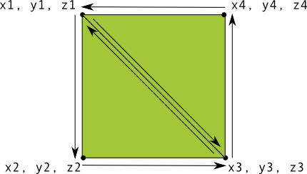
図 1. 2 つの三角形を使った正方形の描画。
この場合も、2 つの三角形について、反時計回りの順に頂点を定義する必要があります。
この形状を表現し、値を ByteBuffer に入れます。これを回避するために
各三角形によって共有される 2 つの座標を 2 回定義するには、描画リストを使用して
OpenGL ES グラフィックス パイプラインは、これらの頂点の描画方法を指定します。この図形を描画するためのコードは次のとおりです。
Kotlin
// number of coordinates per vertex in this array
const val COORDS_PER_VERTEX = 3
var squareCoords = floatArrayOf(
        -0.5f,  0.5f, 0.0f,      // top left
        -0.5f, -0.5f, 0.0f,      // bottom left
         0.5f, -0.5f, 0.0f,      // bottom right
         0.5f,  0.5f, 0.0f       // top right
)

class Square2 {

    private val drawOrder = shortArrayOf(0, 1, 2, 0, 2, 3) // order to draw vertices

    // initialize vertex byte buffer for shape coordinates
    private val vertexBuffer: FloatBuffer =
            // (# of coordinate values * 4 bytes per float)
            ByteBuffer.allocateDirect(squareCoords.size * 4).run {
                order(ByteOrder.nativeOrder())
                asFloatBuffer().apply {
                    put(squareCoords)
                    position(0)
                }
            }

    // initialize byte buffer for the draw list
    private val drawListBuffer: ShortBuffer =
            // (# of coordinate values * 2 bytes per short)
            ByteBuffer.allocateDirect(drawOrder.size * 2).run {
                order(ByteOrder.nativeOrder())
                asShortBuffer().apply {
                    put(drawOrder)
                    position(0)
                }
            }
}
Java
public class Square {

    private FloatBuffer vertexBuffer;
    private ShortBuffer drawListBuffer;

    // number of coordinates per vertex in this array
    static final int COORDS_PER_VERTEX = 3;
    static float squareCoords[] = {
            -0.5f,  0.5f, 0.0f,   // top left
            -0.5f, -0.5f, 0.0f,   // bottom left
             0.5f, -0.5f, 0.0f,   // bottom right
             0.5f,  0.5f, 0.0f }; // top right

    private short drawOrder[] = { 0, 1, 2, 0, 2, 3 }; // order to draw vertices

    public Square() {
        // initialize vertex byte buffer for shape coordinates
        ByteBuffer bb = ByteBuffer.allocateDirect(
        // (# of coordinate values * 4 bytes per float)
                squareCoords.length * 4);
        bb.order(ByteOrder.nativeOrder());
        vertexBuffer = bb.asFloatBuffer();
        vertexBuffer.put(squareCoords);
        vertexBuffer.position(0);

        // initialize byte buffer for the draw list
        ByteBuffer dlb = ByteBuffer.allocateDirect(
        // (# of coordinate values * 2 bytes per short)
                drawOrder.length * 2);
        dlb.order(ByteOrder.nativeOrder());
        drawListBuffer = dlb.asShortBuffer();
        drawListBuffer.put(drawOrder);
        drawListBuffer.position(0);
    }
}
この例では、OpenGL でより複雑な図形を作成する方法を説明しています。イン 一般的には、三角形のコレクションを使用してオブジェクトを描画します。次のレッスンでは、Google Chat で 画面上に描画します