Apply projection and camera views
Stay organized with collections
Save and categorize content based on your preferences.
In the OpenGL ES environment, projection and camera views allow you to display drawn objects in a
way that more closely resembles how you see physical objects with your eyes. This simulation of
physical viewing is done with mathematical transformations of drawn object coordinates:
- Projection - This transformation adjusts the coordinates of drawn objects based on
the width and height of the
GLSurfaceView
where they are displayed. Without
this calculation, objects drawn by OpenGL ES are skewed by the unequal proportions of the view
window. A projection transformation typically only has to be calculated when the proportions of the
OpenGL view are established or changed in the onSurfaceChanged()
method of your renderer. For more information about OpenGL ES projections and
coordinate mapping, see
Mapping coordinates for drawn
objects.
- Camera View - This transformation adjusts the coordinates of drawn objects based on a
virtual camera position. It’s important to note that OpenGL ES does not define an actual camera
object, but instead provides utility methods that simulate a camera by transforming the display of
drawn objects. A camera view transformation might be calculated only once when you establish your
GLSurfaceView
, or might change dynamically based on user actions or your
application’s function.
This lesson describes how to create a projection and camera view and apply it to shapes drawn in
your GLSurfaceView
.
Define a projection
The data for a projection transformation is calculated in the onSurfaceChanged()
method of your GLSurfaceView.Renderer
class. The following example code
takes the height and width of the GLSurfaceView
and uses it to populate a
projection transformation Matrix
using the Matrix.frustumM()
method:
Kotlin
// vPMatrix is an abbreviation for "Model View Projection Matrix"
private val vPMatrix = FloatArray(16)
private val projectionMatrix = FloatArray(16)
private val viewMatrix = FloatArray(16)
override fun onSurfaceChanged(unused: GL10, width: Int, height: Int) {
GLES20.glViewport(0, 0, width, height)
val ratio: Float = width.toFloat() / height.toFloat()
// this projection matrix is applied to object coordinates
// in the onDrawFrame() method
Matrix.frustumM(projectionMatrix, 0, -ratio, ratio, -1f, 1f, 3f, 7f)
}
Java
// vPMatrix is an abbreviation for "Model View Projection Matrix"
private final float[] vPMatrix = new float[16];
private final float[] projectionMatrix = new float[16];
private final float[] viewMatrix = new float[16];
@Override
public void onSurfaceChanged(GL10 unused, int width, int height) {
GLES20.glViewport(0, 0, width, height);
float ratio = (float) width / height;
// this projection matrix is applied to object coordinates
// in the onDrawFrame() method
Matrix.frustumM(projectionMatrix, 0, -ratio, ratio, -1, 1, 3, 7);
}
This code populates a projection matrix, mProjectionMatrix
which you can then combine
with a camera view transformation in the onDrawFrame()
method, which is shown in the next section.
Note: Just applying a projection transformation to your
drawing objects typically results in a very empty display. In general, you must also apply a camera
view transformation in order for anything to show up on screen.
Define a camera view
Complete the process of transforming your drawn objects by adding a camera view transformation as
part of the drawing process in your renderer. In the following example code, the camera view
transformation is calculated using the Matrix.setLookAtM()
method and then combined with the previously calculated projection matrix. The combined
transformation matrices are then passed to the drawn shape.
Kotlin
override fun onDrawFrame(unused: GL10) {
...
// Set the camera position (View matrix)
Matrix.setLookAtM(viewMatrix, 0, 0f, 0f, 3f, 0f, 0f, 0f, 0f, 1.0f, 0.0f)
// Calculate the projection and view transformation
Matrix.multiplyMM(vPMatrix, 0, projectionMatrix, 0, viewMatrix, 0)
// Draw shape
triangle.draw(vPMatrix)
Java
@Override
public void onDrawFrame(GL10 unused) {
...
// Set the camera position (View matrix)
Matrix.setLookAtM(viewMatrix, 0, 0, 0, 3, 0f, 0f, 0f, 0f, 1.0f, 0.0f);
// Calculate the projection and view transformation
Matrix.multiplyMM(vPMatrix, 0, projectionMatrix, 0, viewMatrix, 0);
// Draw shape
triangle.draw(vPMatrix);
}
In order to use the combined projection and camera view transformation matrix shown in the
previews sections, first add a matrix variable to the vertex shader previously defined
in the Triangle
class:
Kotlin
class Triangle {
private val vertexShaderCode =
// This matrix member variable provides a hook to manipulate
// the coordinates of the objects that use this vertex shader
"uniform mat4 uMVPMatrix;" +
"attribute vec4 vPosition;" +
"void main() {" +
// the matrix must be included as a modifier of gl_Position
// Note that the uMVPMatrix factor *must be first* in order
// for the matrix multiplication product to be correct.
" gl_Position = uMVPMatrix * vPosition;" +
"}"
// Use to access and set the view transformation
private var vPMatrixHandle: Int = 0
...
}
Java
public class Triangle {
private final String vertexShaderCode =
// This matrix member variable provides a hook to manipulate
// the coordinates of the objects that use this vertex shader
"uniform mat4 uMVPMatrix;" +
"attribute vec4 vPosition;" +
"void main() {" +
// the matrix must be included as a modifier of gl_Position
// Note that the uMVPMatrix factor *must be first* in order
// for the matrix multiplication product to be correct.
" gl_Position = uMVPMatrix * vPosition;" +
"}";
// Use to access and set the view transformation
private int vPMatrixHandle;
...
}
Next, modify the draw()
method of your graphic objects to accept the combined
transformation matrix and apply it to the shape:
Kotlin
fun draw(mvpMatrix: FloatArray) { // pass in the calculated transformation matrix
...
// get handle to shape's transformation matrix
vPMatrixHandle = GLES20.glGetUniformLocation(mProgram, "uMVPMatrix")
// Pass the projection and view transformation to the shader
GLES20.glUniformMatrix4fv(vPMatrixHandle, 1, false, mvpMatrix, 0)
// Draw the triangle
GLES20.glDrawArrays(GLES20.GL_TRIANGLES, 0, vertexCount)
// Disable vertex array
GLES20.glDisableVertexAttribArray(positionHandle)
}
Java
public void draw(float[] mvpMatrix) { // pass in the calculated transformation matrix
...
// get handle to shape's transformation matrix
vPMatrixHandle = GLES20.glGetUniformLocation(mProgram, "uMVPMatrix");
// Pass the projection and view transformation to the shader
GLES20.glUniformMatrix4fv(vPMatrixHandle, 1, false, mvpMatrix, 0);
// Draw the triangle
GLES20.glDrawArrays(GLES20.GL_TRIANGLES, 0, vertexCount);
// Disable vertex array
GLES20.glDisableVertexAttribArray(positionHandle);
}
Once you have correctly calculated and applied the projection and camera view transformations,
your graphic objects are drawn in correct proportions and should look like this:
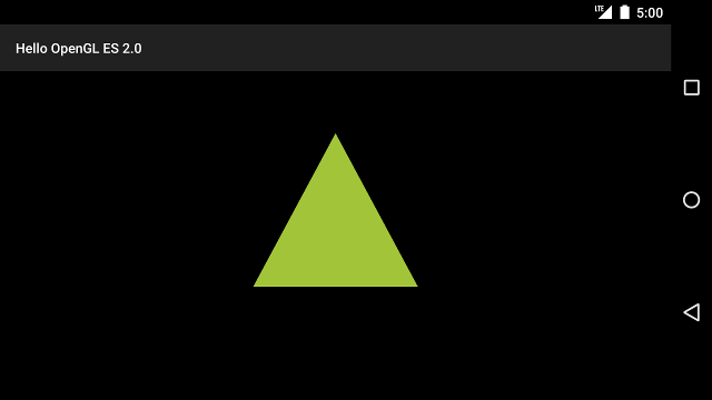
Figure 1. Triangle drawn with a projection and camera view applied.
Now that you have an application that displays your shapes in correct proportions, it's time to
add motion to your shapes.
Content and code samples on this page are subject to the licenses described in the Content License. Java and OpenJDK are trademarks or registered trademarks of Oracle and/or its affiliates.
Last updated 2024-08-26 UTC.
[[["Easy to understand","easyToUnderstand","thumb-up"],["Solved my problem","solvedMyProblem","thumb-up"],["Other","otherUp","thumb-up"]],[["Missing the information I need","missingTheInformationINeed","thumb-down"],["Too complicated / too many steps","tooComplicatedTooManySteps","thumb-down"],["Out of date","outOfDate","thumb-down"],["Samples / code issue","samplesCodeIssue","thumb-down"],["Other","otherDown","thumb-down"]],["Last updated 2024-08-26 UTC."],[],[],null,["# Apply projection and camera views\n\nIn the OpenGL ES environment, projection and camera views allow you to display drawn objects in a\nway that more closely resembles how you see physical objects with your eyes. This simulation of\nphysical viewing is done with mathematical transformations of drawn object coordinates:\n\n- *Projection* - This transformation adjusts the coordinates of drawn objects based on the width and height of the [GLSurfaceView](/reference/android/opengl/GLSurfaceView) where they are displayed. Without this calculation, objects drawn by OpenGL ES are skewed by the unequal proportions of the view window. A projection transformation typically only has to be calculated when the proportions of the OpenGL view are established or changed in the [onSurfaceChanged()](/reference/android/opengl/GLSurfaceView.Renderer#onSurfaceChanged(javax.microedition.khronos.opengles.GL10, int, int)) method of your renderer. For more information about OpenGL ES projections and coordinate mapping, see [Mapping coordinates for drawn\n objects](/develop/ui/views/graphics/opengl/about-opengl#coordinate-mapping).\n- *Camera View* - This transformation adjusts the coordinates of drawn objects based on a virtual camera position. It's important to note that OpenGL ES does not define an actual camera object, but instead provides utility methods that simulate a camera by transforming the display of drawn objects. A camera view transformation might be calculated only once when you establish your [GLSurfaceView](/reference/android/opengl/GLSurfaceView), or might change dynamically based on user actions or your application's function.\n\nThis lesson describes how to create a projection and camera view and apply it to shapes drawn in\nyour [GLSurfaceView](/reference/android/opengl/GLSurfaceView).\n\nDefine a projection\n-------------------\n\nThe data for a projection transformation is calculated in the [onSurfaceChanged()](/reference/android/opengl/GLSurfaceView.Renderer#onSurfaceChanged(javax.microedition.khronos.opengles.GL10, int, int))\nmethod of your [GLSurfaceView.Renderer](/reference/android/opengl/GLSurfaceView.Renderer) class. The following example code\ntakes the height and width of the [GLSurfaceView](/reference/android/opengl/GLSurfaceView) and uses it to populate a\nprojection transformation [Matrix](/reference/android/opengl/Matrix) using the [Matrix.frustumM()](/reference/android/opengl/Matrix#frustumM(float[], int, float, float, float, float, float, float)) method: \n\n### Kotlin\n\n```kotlin\n// vPMatrix is an abbreviation for \"Model View Projection Matrix\"\nprivate val vPMatrix = FloatArray(16)\nprivate val projectionMatrix = FloatArray(16)\nprivate val viewMatrix = FloatArray(16)\n\noverride fun onSurfaceChanged(unused: GL10, width: Int, height: Int) {\n GLES20.glViewport(0, 0, width, height)\n\n val ratio: Float = width.toFloat() / height.toFloat()\n\n // this projection matrix is applied to object coordinates\n // in the onDrawFrame() method\n Matrix.frustumM(projectionMatrix, 0, -ratio, ratio, -1f, 1f, 3f, 7f)\n}\n```\n\n### Java\n\n```java\n// vPMatrix is an abbreviation for \"Model View Projection Matrix\"\nprivate final float[] vPMatrix = new float[16];\nprivate final float[] projectionMatrix = new float[16];\nprivate final float[] viewMatrix = new float[16];\n\n@Override\npublic void onSurfaceChanged(GL10 unused, int width, int height) {\n GLES20.glViewport(0, 0, width, height);\n\n float ratio = (float) width / height;\n\n // this projection matrix is applied to object coordinates\n // in the onDrawFrame() method\n Matrix.frustumM(projectionMatrix, 0, -ratio, ratio, -1, 1, 3, 7);\n}\n```\n\nThis code populates a projection matrix, `mProjectionMatrix` which you can then combine\nwith a camera view transformation in the [onDrawFrame()](/reference/android/opengl/GLSurfaceView.Renderer#onDrawFrame(javax.microedition.khronos.opengles.GL10)) method, which is shown in the next section.\n\n**Note:** Just applying a projection transformation to your\ndrawing objects typically results in a very empty display. In general, you must also apply a camera\nview transformation in order for anything to show up on screen.\n\nDefine a camera view\n--------------------\n\nComplete the process of transforming your drawn objects by adding a camera view transformation as\npart of the drawing process in your renderer. In the following example code, the camera view\ntransformation is calculated using the [Matrix.setLookAtM()](/reference/android/opengl/Matrix#setLookAtM(float[], int, float, float, float, float, float, float, float, float, float))\nmethod and then combined with the previously calculated projection matrix. The combined\ntransformation matrices are then passed to the drawn shape. \n\n### Kotlin\n\n```kotlin\noverride fun onDrawFrame(unused: GL10) {\n ...\n // Set the camera position (View matrix)\n Matrix.setLookAtM(viewMatrix, 0, 0f, 0f, 3f, 0f, 0f, 0f, 0f, 1.0f, 0.0f)\n\n // Calculate the projection and view transformation\n Matrix.multiplyMM(vPMatrix, 0, projectionMatrix, 0, viewMatrix, 0)\n\n // Draw shape\n triangle.draw(vPMatrix)\n```\n\n### Java\n\n```java\n@Override\npublic void onDrawFrame(GL10 unused) {\n ...\n // Set the camera position (View matrix)\n Matrix.setLookAtM(viewMatrix, 0, 0, 0, 3, 0f, 0f, 0f, 0f, 1.0f, 0.0f);\n\n // Calculate the projection and view transformation\n Matrix.multiplyMM(vPMatrix, 0, projectionMatrix, 0, viewMatrix, 0);\n\n // Draw shape\n triangle.draw(vPMatrix);\n}\n```\n\nApply projection and camera transformations\n-------------------------------------------\n\nIn order to use the combined projection and camera view transformation matrix shown in the\npreviews sections, first add a matrix variable to the *vertex shader* previously defined\nin the `Triangle` class: \n\n### Kotlin\n\n```kotlin\nclass Triangle {\n\n private val vertexShaderCode =\n // This matrix member variable provides a hook to manipulate\n // the coordinates of the objects that use this vertex shader\n \"uniform mat4 uMVPMatrix;\" +\n \"attribute vec4 vPosition;\" +\n \"void main() {\" +\n // the matrix must be included as a modifier of gl_Position\n // Note that the uMVPMatrix factor *must be first* in order\n // for the matrix multiplication product to be correct.\n \" gl_Position = uMVPMatrix * vPosition;\" +\n \"}\"\n\n // Use to access and set the view transformation\n private var vPMatrixHandle: Int = 0\n\n ...\n}\n```\n\n### Java\n\n```java\npublic class Triangle {\n\n private final String vertexShaderCode =\n // This matrix member variable provides a hook to manipulate\n // the coordinates of the objects that use this vertex shader\n \"uniform mat4 uMVPMatrix;\" +\n \"attribute vec4 vPosition;\" +\n \"void main() {\" +\n // the matrix must be included as a modifier of gl_Position\n // Note that the uMVPMatrix factor *must be first* in order\n // for the matrix multiplication product to be correct.\n \" gl_Position = uMVPMatrix * vPosition;\" +\n \"}\";\n\n // Use to access and set the view transformation\n private int vPMatrixHandle;\n\n ...\n}\n```\n\nNext, modify the `draw()` method of your graphic objects to accept the combined\ntransformation matrix and apply it to the shape: \n\n### Kotlin\n\n```kotlin\nfun draw(mvpMatrix: FloatArray) { // pass in the calculated transformation matrix\n ...\n\n // get handle to shape's transformation matrix\n vPMatrixHandle = GLES20.glGetUniformLocation(mProgram, \"uMVPMatrix\")\n\n // Pass the projection and view transformation to the shader\n GLES20.glUniformMatrix4fv(vPMatrixHandle, 1, false, mvpMatrix, 0)\n\n // Draw the triangle\n GLES20.glDrawArrays(GLES20.GL_TRIANGLES, 0, vertexCount)\n\n // Disable vertex array\n GLES20.glDisableVertexAttribArray(positionHandle)\n}\n```\n\n### Java\n\n```java\npublic void draw(float[] mvpMatrix) { // pass in the calculated transformation matrix\n ...\n\n // get handle to shape's transformation matrix\n vPMatrixHandle = GLES20.glGetUniformLocation(mProgram, \"uMVPMatrix\");\n\n // Pass the projection and view transformation to the shader\n GLES20.glUniformMatrix4fv(vPMatrixHandle, 1, false, mvpMatrix, 0);\n\n // Draw the triangle\n GLES20.glDrawArrays(GLES20.GL_TRIANGLES, 0, vertexCount);\n\n // Disable vertex array\n GLES20.glDisableVertexAttribArray(positionHandle);\n}\n```\n\nOnce you have correctly calculated and applied the projection and camera view transformations,\nyour graphic objects are drawn in correct proportions and should look like this:\n\n\n**Figure 1.** Triangle drawn with a projection and camera view applied.\n\nNow that you have an application that displays your shapes in correct proportions, it's time to\nadd motion to your shapes."]]