Cómo aplicar vistas de cámara y proyección
Organiza tus páginas con colecciones
Guarda y categoriza el contenido según tus preferencias.
En el entorno de OpenGL ES, las vistas de proyección y cámara permiten mostrar objetos dibujados en una
que se asemeja más al modo en que ves los objetos físicos con los ojos. Esta simulación de
la visualización física se realiza con transformaciones matemáticas de coordenadas de objetos dibujados:
- Proyección: Esta transformación ajusta las coordenadas de los objetos dibujados según
el ancho y la altura de
GLSurfaceView
donde se muestran Sin
este cálculo, los objetos dibujados por OpenGL ES están sesgados por las proporciones desiguales de la vista
en la ventana modal. En general, una transformación de proyección solo debe calcularse cuando las proporciones de la
se establecen o cambian en el método onSurfaceChanged()
de tu procesador. Para obtener más información sobre las proyecciones de OpenGL ES y
mapeo de coordenadas, consulta
Cómo asignar coordenadas para dibujos
objetos.
- Vista de cámara: esta transformación ajusta las coordenadas de los objetos dibujados según una
la posición de la cámara virtual. Es importante tener en cuenta que OpenGL ES no define un modelo
sino que proporciona métodos de utilidades que simulan una cámara transformando la visualización de
dibujados. Una transformación de vista de cámara se puede calcular solo una vez cuando estableces tu
GLSurfaceView
o puede cambiar de forma dinámica según las acciones del usuario o tu
función de la aplicación.
En esta lección, se describe cómo crear una vista de cámara y proyección, y cómo aplicarla a las formas dibujadas en
tu GLSurfaceView
.
Cómo definir una proyección
Los datos para una transformación de proyección se calculan en onSurfaceChanged()
.
de tu clase GLSurfaceView.Renderer
. El siguiente código de ejemplo
toma la altura y el ancho de la GLSurfaceView
y la usa para propagar
Transformación de proyección Matrix
con el método Matrix.frustumM()
:
Kotlin
// vPMatrix is an abbreviation for "Model View Projection Matrix"
private val vPMatrix = FloatArray(16)
private val projectionMatrix = FloatArray(16)
private val viewMatrix = FloatArray(16)
override fun onSurfaceChanged(unused: GL10, width: Int, height: Int) {
GLES20.glViewport(0, 0, width, height)
val ratio: Float = width.toFloat() / height.toFloat()
// this projection matrix is applied to object coordinates
// in the onDrawFrame() method
Matrix.frustumM(projectionMatrix, 0, -ratio, ratio, -1f, 1f, 3f, 7f)
}
Java
// vPMatrix is an abbreviation for "Model View Projection Matrix"
private final float[] vPMatrix = new float[16];
private final float[] projectionMatrix = new float[16];
private final float[] viewMatrix = new float[16];
@Override
public void onSurfaceChanged(GL10 unused, int width, int height) {
GLES20.glViewport(0, 0, width, height);
float ratio = (float) width / height;
// this projection matrix is applied to object coordinates
// in the onDrawFrame() method
Matrix.frustumM(projectionMatrix, 0, -ratio, ratio, -1, 1, 3, 7);
}
Este código propaga una matriz de proyección, mProjectionMatrix
, que luego puedes combinar.
con una transformación de vista de cámara en el método onDrawFrame()
, que se muestra en la siguiente sección
Nota: Solo aplica una transformación de proyección a tu
los objetos de dibujo generalmente dan como resultado una pantalla muy vacía. En general, también debes aplicar una cámara
la transformación de datos
para que algo aparezca en la pantalla.
Define una vista de cámara
Completa el proceso de transformación de los objetos dibujados; para ello, agrega una transformación de vista de cámara como
parte del proceso de dibujo en tu renderizador. En el siguiente código de ejemplo, la vista de cámara
transformación se calcula con Matrix.setLookAtM()
y, luego, combinarse con la matriz de proyección calculada previamente. La combinación
las matrices de transformación se pasan a la forma dibujada.
Kotlin
override fun onDrawFrame(unused: GL10) {
...
// Set the camera position (View matrix)
Matrix.setLookAtM(viewMatrix, 0, 0f, 0f, 3f, 0f, 0f, 0f, 0f, 1.0f, 0.0f)
// Calculate the projection and view transformation
Matrix.multiplyMM(vPMatrix, 0, projectionMatrix, 0, viewMatrix, 0)
// Draw shape
triangle.draw(vPMatrix)
Java
@Override
public void onDrawFrame(GL10 unused) {
...
// Set the camera position (View matrix)
Matrix.setLookAtM(viewMatrix, 0, 0, 0, 3, 0f, 0f, 0f, 0f, 1.0f, 0.0f);
// Calculate the projection and view transformation
Matrix.multiplyMM(vPMatrix, 0, projectionMatrix, 0, viewMatrix, 0);
// Draw shape
triangle.draw(vPMatrix);
}
Para usar la matriz de transformación combinada de proyección y vista de cámara que se muestra en la
primero, agrega una variable de matriz al sombreador de vértices definido previamente
En la clase Triangle
:
Kotlin
class Triangle {
private val vertexShaderCode =
// This matrix member variable provides a hook to manipulate
// the coordinates of the objects that use this vertex shader
"uniform mat4 uMVPMatrix;" +
"attribute vec4 vPosition;" +
"void main() {" +
// the matrix must be included as a modifier of gl_Position
// Note that the uMVPMatrix factor *must be first* in order
// for the matrix multiplication product to be correct.
" gl_Position = uMVPMatrix * vPosition;" +
"}"
// Use to access and set the view transformation
private var vPMatrixHandle: Int = 0
...
}
Java
public class Triangle {
private final String vertexShaderCode =
// This matrix member variable provides a hook to manipulate
// the coordinates of the objects that use this vertex shader
"uniform mat4 uMVPMatrix;" +
"attribute vec4 vPosition;" +
"void main() {" +
// the matrix must be included as a modifier of gl_Position
// Note that the uMVPMatrix factor *must be first* in order
// for the matrix multiplication product to be correct.
" gl_Position = uMVPMatrix * vPosition;" +
"}";
// Use to access and set the view transformation
private int vPMatrixHandle;
...
}
A continuación, modifica el método draw()
de tus objetos gráficos para aceptar las combinaciones
de transformación y aplícala a la siguiente forma:
Kotlin
fun draw(mvpMatrix: FloatArray) { // pass in the calculated transformation matrix
...
// get handle to shape's transformation matrix
vPMatrixHandle = GLES20.glGetUniformLocation(mProgram, "uMVPMatrix")
// Pass the projection and view transformation to the shader
GLES20.glUniformMatrix4fv(vPMatrixHandle, 1, false, mvpMatrix, 0)
// Draw the triangle
GLES20.glDrawArrays(GLES20.GL_TRIANGLES, 0, vertexCount)
// Disable vertex array
GLES20.glDisableVertexAttribArray(positionHandle)
}
Java
public void draw(float[] mvpMatrix) { // pass in the calculated transformation matrix
...
// get handle to shape's transformation matrix
vPMatrixHandle = GLES20.glGetUniformLocation(mProgram, "uMVPMatrix");
// Pass the projection and view transformation to the shader
GLES20.glUniformMatrix4fv(vPMatrixHandle, 1, false, mvpMatrix, 0);
// Draw the triangle
GLES20.glDrawArrays(GLES20.GL_TRIANGLES, 0, vertexCount);
// Disable vertex array
GLES20.glDisableVertexAttribArray(positionHandle);
}
Una vez que hayas calculado y aplicado correctamente las transformaciones de proyección y vista de cámara,
tus objetos gráficos se dibujan en proporciones correctas y deberían verse de la siguiente manera:
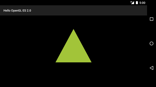
Figura 1: Triángulo dibujado con una vista de cámara y proyección aplicada
Ahora que tienes una aplicación que muestra las formas en las proporciones correctas, es hora de
agregar movimiento a tus formas.
El contenido y las muestras de código que aparecen en esta página están sujetas a las licencias que se describen en la Licencia de Contenido. Java y OpenJDK son marcas registradas de Oracle o sus afiliados.
Última actualización: 2025-07-27 (UTC)
[[["Fácil de comprender","easyToUnderstand","thumb-up"],["Resolvió mi problema","solvedMyProblem","thumb-up"],["Otro","otherUp","thumb-up"]],[["Falta la información que necesito","missingTheInformationINeed","thumb-down"],["Muy complicado o demasiados pasos","tooComplicatedTooManySteps","thumb-down"],["Desactualizado","outOfDate","thumb-down"],["Problema de traducción","translationIssue","thumb-down"],["Problema con las muestras o los códigos","samplesCodeIssue","thumb-down"],["Otro","otherDown","thumb-down"]],["Última actualización: 2025-07-27 (UTC)"],[],[],null,["# Apply projection and camera views\n\nIn the OpenGL ES environment, projection and camera views allow you to display drawn objects in a\nway that more closely resembles how you see physical objects with your eyes. This simulation of\nphysical viewing is done with mathematical transformations of drawn object coordinates:\n\n- *Projection* - This transformation adjusts the coordinates of drawn objects based on the width and height of the [GLSurfaceView](/reference/android/opengl/GLSurfaceView) where they are displayed. Without this calculation, objects drawn by OpenGL ES are skewed by the unequal proportions of the view window. A projection transformation typically only has to be calculated when the proportions of the OpenGL view are established or changed in the [onSurfaceChanged()](/reference/android/opengl/GLSurfaceView.Renderer#onSurfaceChanged(javax.microedition.khronos.opengles.GL10, int, int)) method of your renderer. For more information about OpenGL ES projections and coordinate mapping, see [Mapping coordinates for drawn\n objects](/develop/ui/views/graphics/opengl/about-opengl#coordinate-mapping).\n- *Camera View* - This transformation adjusts the coordinates of drawn objects based on a virtual camera position. It's important to note that OpenGL ES does not define an actual camera object, but instead provides utility methods that simulate a camera by transforming the display of drawn objects. A camera view transformation might be calculated only once when you establish your [GLSurfaceView](/reference/android/opengl/GLSurfaceView), or might change dynamically based on user actions or your application's function.\n\nThis lesson describes how to create a projection and camera view and apply it to shapes drawn in\nyour [GLSurfaceView](/reference/android/opengl/GLSurfaceView).\n\nDefine a projection\n-------------------\n\nThe data for a projection transformation is calculated in the [onSurfaceChanged()](/reference/android/opengl/GLSurfaceView.Renderer#onSurfaceChanged(javax.microedition.khronos.opengles.GL10, int, int))\nmethod of your [GLSurfaceView.Renderer](/reference/android/opengl/GLSurfaceView.Renderer) class. The following example code\ntakes the height and width of the [GLSurfaceView](/reference/android/opengl/GLSurfaceView) and uses it to populate a\nprojection transformation [Matrix](/reference/android/opengl/Matrix) using the [Matrix.frustumM()](/reference/android/opengl/Matrix#frustumM(float[], int, float, float, float, float, float, float)) method: \n\n### Kotlin\n\n```kotlin\n// vPMatrix is an abbreviation for \"Model View Projection Matrix\"\nprivate val vPMatrix = FloatArray(16)\nprivate val projectionMatrix = FloatArray(16)\nprivate val viewMatrix = FloatArray(16)\n\noverride fun onSurfaceChanged(unused: GL10, width: Int, height: Int) {\n GLES20.glViewport(0, 0, width, height)\n\n val ratio: Float = width.toFloat() / height.toFloat()\n\n // this projection matrix is applied to object coordinates\n // in the onDrawFrame() method\n Matrix.frustumM(projectionMatrix, 0, -ratio, ratio, -1f, 1f, 3f, 7f)\n}\n```\n\n### Java\n\n```java\n// vPMatrix is an abbreviation for \"Model View Projection Matrix\"\nprivate final float[] vPMatrix = new float[16];\nprivate final float[] projectionMatrix = new float[16];\nprivate final float[] viewMatrix = new float[16];\n\n@Override\npublic void onSurfaceChanged(GL10 unused, int width, int height) {\n GLES20.glViewport(0, 0, width, height);\n\n float ratio = (float) width / height;\n\n // this projection matrix is applied to object coordinates\n // in the onDrawFrame() method\n Matrix.frustumM(projectionMatrix, 0, -ratio, ratio, -1, 1, 3, 7);\n}\n```\n\nThis code populates a projection matrix, `mProjectionMatrix` which you can then combine\nwith a camera view transformation in the [onDrawFrame()](/reference/android/opengl/GLSurfaceView.Renderer#onDrawFrame(javax.microedition.khronos.opengles.GL10)) method, which is shown in the next section.\n\n**Note:** Just applying a projection transformation to your\ndrawing objects typically results in a very empty display. In general, you must also apply a camera\nview transformation in order for anything to show up on screen.\n\nDefine a camera view\n--------------------\n\nComplete the process of transforming your drawn objects by adding a camera view transformation as\npart of the drawing process in your renderer. In the following example code, the camera view\ntransformation is calculated using the [Matrix.setLookAtM()](/reference/android/opengl/Matrix#setLookAtM(float[], int, float, float, float, float, float, float, float, float, float))\nmethod and then combined with the previously calculated projection matrix. The combined\ntransformation matrices are then passed to the drawn shape. \n\n### Kotlin\n\n```kotlin\noverride fun onDrawFrame(unused: GL10) {\n ...\n // Set the camera position (View matrix)\n Matrix.setLookAtM(viewMatrix, 0, 0f, 0f, 3f, 0f, 0f, 0f, 0f, 1.0f, 0.0f)\n\n // Calculate the projection and view transformation\n Matrix.multiplyMM(vPMatrix, 0, projectionMatrix, 0, viewMatrix, 0)\n\n // Draw shape\n triangle.draw(vPMatrix)\n```\n\n### Java\n\n```java\n@Override\npublic void onDrawFrame(GL10 unused) {\n ...\n // Set the camera position (View matrix)\n Matrix.setLookAtM(viewMatrix, 0, 0, 0, 3, 0f, 0f, 0f, 0f, 1.0f, 0.0f);\n\n // Calculate the projection and view transformation\n Matrix.multiplyMM(vPMatrix, 0, projectionMatrix, 0, viewMatrix, 0);\n\n // Draw shape\n triangle.draw(vPMatrix);\n}\n```\n\nApply projection and camera transformations\n-------------------------------------------\n\nIn order to use the combined projection and camera view transformation matrix shown in the\npreviews sections, first add a matrix variable to the *vertex shader* previously defined\nin the `Triangle` class: \n\n### Kotlin\n\n```kotlin\nclass Triangle {\n\n private val vertexShaderCode =\n // This matrix member variable provides a hook to manipulate\n // the coordinates of the objects that use this vertex shader\n \"uniform mat4 uMVPMatrix;\" +\n \"attribute vec4 vPosition;\" +\n \"void main() {\" +\n // the matrix must be included as a modifier of gl_Position\n // Note that the uMVPMatrix factor *must be first* in order\n // for the matrix multiplication product to be correct.\n \" gl_Position = uMVPMatrix * vPosition;\" +\n \"}\"\n\n // Use to access and set the view transformation\n private var vPMatrixHandle: Int = 0\n\n ...\n}\n```\n\n### Java\n\n```java\npublic class Triangle {\n\n private final String vertexShaderCode =\n // This matrix member variable provides a hook to manipulate\n // the coordinates of the objects that use this vertex shader\n \"uniform mat4 uMVPMatrix;\" +\n \"attribute vec4 vPosition;\" +\n \"void main() {\" +\n // the matrix must be included as a modifier of gl_Position\n // Note that the uMVPMatrix factor *must be first* in order\n // for the matrix multiplication product to be correct.\n \" gl_Position = uMVPMatrix * vPosition;\" +\n \"}\";\n\n // Use to access and set the view transformation\n private int vPMatrixHandle;\n\n ...\n}\n```\n\nNext, modify the `draw()` method of your graphic objects to accept the combined\ntransformation matrix and apply it to the shape: \n\n### Kotlin\n\n```kotlin\nfun draw(mvpMatrix: FloatArray) { // pass in the calculated transformation matrix\n ...\n\n // get handle to shape's transformation matrix\n vPMatrixHandle = GLES20.glGetUniformLocation(mProgram, \"uMVPMatrix\")\n\n // Pass the projection and view transformation to the shader\n GLES20.glUniformMatrix4fv(vPMatrixHandle, 1, false, mvpMatrix, 0)\n\n // Draw the triangle\n GLES20.glDrawArrays(GLES20.GL_TRIANGLES, 0, vertexCount)\n\n // Disable vertex array\n GLES20.glDisableVertexAttribArray(positionHandle)\n}\n```\n\n### Java\n\n```java\npublic void draw(float[] mvpMatrix) { // pass in the calculated transformation matrix\n ...\n\n // get handle to shape's transformation matrix\n vPMatrixHandle = GLES20.glGetUniformLocation(mProgram, \"uMVPMatrix\");\n\n // Pass the projection and view transformation to the shader\n GLES20.glUniformMatrix4fv(vPMatrixHandle, 1, false, mvpMatrix, 0);\n\n // Draw the triangle\n GLES20.glDrawArrays(GLES20.GL_TRIANGLES, 0, vertexCount);\n\n // Disable vertex array\n GLES20.glDisableVertexAttribArray(positionHandle);\n}\n```\n\nOnce you have correctly calculated and applied the projection and camera view transformations,\nyour graphic objects are drawn in correct proportions and should look like this:\n\n\n**Figure 1.** Triangle drawn with a projection and camera view applied.\n\nNow that you have an application that displays your shapes in correct proportions, it's time to\nadd motion to your shapes."]]