Appliquer des vues de caméra et des projections
Restez organisé à l'aide des collections
Enregistrez et classez les contenus selon vos préférences.
Dans l'environnement OpenGL ES, la projection et les vues de caméra vous permettent d'afficher les objets dessinés dans un
qui ressemble davantage à la façon dont vous
voyez des objets physiques avec vos yeux. Cette simulation de
l'affichage physique se fait par le biais de transformations mathématiques des coordonnées des objets dessinés:
- Projection : cette transformation ajuste les coordonnées des objets dessinés en fonction de
la largeur et la hauteur du
GLSurfaceView
où elles sont affichées ; Sans
ce calcul, les objets dessinés par OpenGL ES sont faussés par les proportions inégales de la vue
fenêtre. En général, une transformation de projection ne doit être calculée que lorsque les proportions des
La vue OpenGL est établie ou modifiée dans la méthode onSurfaceChanged()
de votre moteur de rendu. Pour en savoir plus sur les projections
OpenGL ES et
la cartographie des coordonnées, consultez
Cartographie des coordonnées
Objets.
- Camera View (Vue de la caméra) : cette transformation ajuste les coordonnées des objets dessinés en fonction d'un
la position de la caméra virtuelle. Il est important de noter qu'OpenGL ES ne définit pas de caméra
mais fournit à la place des méthodes utilitaires qui simulent un appareil photo en transformant l'affichage
des objets dessinés. Une transformation de vue de caméra peut être calculée une seule fois lorsque vous établissez votre
GLSurfaceView
, ou changer de façon dynamique en fonction des actions des utilisateurs ou de vos
la fonction d'application.
Cette leçon explique comment créer une projection et une vue de caméra, et comment les appliquer aux formes dessinées dans
votre GLSurfaceView
.
Définir une projection
Les données d'une transformation de projection sont calculées dans onSurfaceChanged()
de la classe GLSurfaceView.Renderer
. L'exemple de code suivant
prend la hauteur et la largeur de l'élément GLSurfaceView
et l'utilise pour remplir une
transformation de projection Matrix
à l'aide de la méthode Matrix.frustumM()
:
Kotlin
// vPMatrix is an abbreviation for "Model View Projection Matrix"
private val vPMatrix = FloatArray(16)
private val projectionMatrix = FloatArray(16)
private val viewMatrix = FloatArray(16)
override fun onSurfaceChanged(unused: GL10, width: Int, height: Int) {
GLES20.glViewport(0, 0, width, height)
val ratio: Float = width.toFloat() / height.toFloat()
// this projection matrix is applied to object coordinates
// in the onDrawFrame() method
Matrix.frustumM(projectionMatrix, 0, -ratio, ratio, -1f, 1f, 3f, 7f)
}
Java
// vPMatrix is an abbreviation for "Model View Projection Matrix"
private final float[] vPMatrix = new float[16];
private final float[] projectionMatrix = new float[16];
private final float[] viewMatrix = new float[16];
@Override
public void onSurfaceChanged(GL10 unused, int width, int height) {
GLES20.glViewport(0, 0, width, height);
float ratio = (float) width / height;
// this projection matrix is applied to object coordinates
// in the onDrawFrame() method
Matrix.frustumM(projectionMatrix, 0, -ratio, ratio, -1, 1, 3, 7);
}
Ce code renseigne une matrice de projection, mProjectionMatrix
, que vous pouvez ensuite combiner
avec une transformation de vue de caméra dans la méthode onDrawFrame()
, comme illustré dans la section suivante.
Remarque:Il suffit d'appliquer une transformation de projection à vos
d'objets dessinent généralement un affichage très vide. En règle générale, vous devez aussi installer
la transformation d'affichage pour que
tout soit affiché à l'écran.
Définir une vue de caméra
Terminez le processus de transformation de vos objets dessinés en ajoutant une transformation de vue de caméra en tant que
du processus de dessin dans votre moteur de rendu. Dans l'exemple de code suivant, la vue de la caméra
est calculée à l'aide de la méthode Matrix.setLookAtM()
.
puis combinés à la matrice de projection calculée précédemment. La combinaison
les matrices de transformation sont ensuite transmises à la forme tracée.
Kotlin
override fun onDrawFrame(unused: GL10) {
...
// Set the camera position (View matrix)
Matrix.setLookAtM(viewMatrix, 0, 0f, 0f, 3f, 0f, 0f, 0f, 0f, 1.0f, 0.0f)
// Calculate the projection and view transformation
Matrix.multiplyMM(vPMatrix, 0, projectionMatrix, 0, viewMatrix, 0)
// Draw shape
triangle.draw(vPMatrix)
Java
@Override
public void onDrawFrame(GL10 unused) {
...
// Set the camera position (View matrix)
Matrix.setLookAtM(viewMatrix, 0, 0, 0, 3, 0f, 0f, 0f, 0f, 1.0f, 0.0f);
// Calculate the projection and view transformation
Matrix.multiplyMM(vPMatrix, 0, projectionMatrix, 0, viewMatrix, 0);
// Draw shape
triangle.draw(vPMatrix);
}
Pour utiliser la matrice de transformation combinée de la projection et de la vue de caméra présentée dans le
affiche un aperçu des sections, commencez par ajouter une variable de matrice au nuanceur de sommets défini précédemment
dans la classe Triangle
:
Kotlin
class Triangle {
private val vertexShaderCode =
// This matrix member variable provides a hook to manipulate
// the coordinates of the objects that use this vertex shader
"uniform mat4 uMVPMatrix;" +
"attribute vec4 vPosition;" +
"void main() {" +
// the matrix must be included as a modifier of gl_Position
// Note that the uMVPMatrix factor *must be first* in order
// for the matrix multiplication product to be correct.
" gl_Position = uMVPMatrix * vPosition;" +
"}"
// Use to access and set the view transformation
private var vPMatrixHandle: Int = 0
...
}
Java
public class Triangle {
private final String vertexShaderCode =
// This matrix member variable provides a hook to manipulate
// the coordinates of the objects that use this vertex shader
"uniform mat4 uMVPMatrix;" +
"attribute vec4 vPosition;" +
"void main() {" +
// the matrix must be included as a modifier of gl_Position
// Note that the uMVPMatrix factor *must be first* in order
// for the matrix multiplication product to be correct.
" gl_Position = uMVPMatrix * vPosition;" +
"}";
// Use to access and set the view transformation
private int vPMatrixHandle;
...
}
Ensuite, modifiez la méthode draw()
de vos objets graphiques pour accepter la combinaison
et appliquez-la à la forme:
Kotlin
fun draw(mvpMatrix: FloatArray) { // pass in the calculated transformation matrix
...
// get handle to shape's transformation matrix
vPMatrixHandle = GLES20.glGetUniformLocation(mProgram, "uMVPMatrix")
// Pass the projection and view transformation to the shader
GLES20.glUniformMatrix4fv(vPMatrixHandle, 1, false, mvpMatrix, 0)
// Draw the triangle
GLES20.glDrawArrays(GLES20.GL_TRIANGLES, 0, vertexCount)
// Disable vertex array
GLES20.glDisableVertexAttribArray(positionHandle)
}
Java
public void draw(float[] mvpMatrix) { // pass in the calculated transformation matrix
...
// get handle to shape's transformation matrix
vPMatrixHandle = GLES20.glGetUniformLocation(mProgram, "uMVPMatrix");
// Pass the projection and view transformation to the shader
GLES20.glUniformMatrix4fv(vPMatrixHandle, 1, false, mvpMatrix, 0);
// Draw the triangle
GLES20.glDrawArrays(GLES20.GL_TRIANGLES, 0, vertexCount);
// Disable vertex array
GLES20.glDisableVertexAttribArray(positionHandle);
}
Une fois que vous avez correctement calculé et appliqué les transformations de projection et de vue de caméra,
vos objets graphiques sont dessinés dans des proportions correctes et doivent se présenter comme suit:
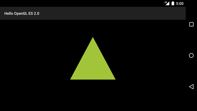
Figure 1 : Triangle dessiné avec une projection et une vue de caméra appliquées.
Maintenant que vous disposez d'une application qui affiche vos formes dans des proportions correctes, il est temps de
ajouter du mouvement
à vos formes.
Le contenu et les exemples de code de cette page sont soumis aux licences décrites dans la Licence de contenu. Java et OpenJDK sont des marques ou des marques déposées d'Oracle et/ou de ses sociétés affiliées.
Dernière mise à jour le 2025/07/27 (UTC).
[[["Facile à comprendre","easyToUnderstand","thumb-up"],["J'ai pu résoudre mon problème","solvedMyProblem","thumb-up"],["Autre","otherUp","thumb-up"]],[["Il n'y a pas l'information dont j'ai besoin","missingTheInformationINeed","thumb-down"],["Trop compliqué/Trop d'étapes","tooComplicatedTooManySteps","thumb-down"],["Obsolète","outOfDate","thumb-down"],["Problème de traduction","translationIssue","thumb-down"],["Mauvais exemple/Erreur de code","samplesCodeIssue","thumb-down"],["Autre","otherDown","thumb-down"]],["Dernière mise à jour le 2025/07/27 (UTC)."],[],[],null,["# Apply projection and camera views\n\nIn the OpenGL ES environment, projection and camera views allow you to display drawn objects in a\nway that more closely resembles how you see physical objects with your eyes. This simulation of\nphysical viewing is done with mathematical transformations of drawn object coordinates:\n\n- *Projection* - This transformation adjusts the coordinates of drawn objects based on the width and height of the [GLSurfaceView](/reference/android/opengl/GLSurfaceView) where they are displayed. Without this calculation, objects drawn by OpenGL ES are skewed by the unequal proportions of the view window. A projection transformation typically only has to be calculated when the proportions of the OpenGL view are established or changed in the [onSurfaceChanged()](/reference/android/opengl/GLSurfaceView.Renderer#onSurfaceChanged(javax.microedition.khronos.opengles.GL10, int, int)) method of your renderer. For more information about OpenGL ES projections and coordinate mapping, see [Mapping coordinates for drawn\n objects](/develop/ui/views/graphics/opengl/about-opengl#coordinate-mapping).\n- *Camera View* - This transformation adjusts the coordinates of drawn objects based on a virtual camera position. It's important to note that OpenGL ES does not define an actual camera object, but instead provides utility methods that simulate a camera by transforming the display of drawn objects. A camera view transformation might be calculated only once when you establish your [GLSurfaceView](/reference/android/opengl/GLSurfaceView), or might change dynamically based on user actions or your application's function.\n\nThis lesson describes how to create a projection and camera view and apply it to shapes drawn in\nyour [GLSurfaceView](/reference/android/opengl/GLSurfaceView).\n\nDefine a projection\n-------------------\n\nThe data for a projection transformation is calculated in the [onSurfaceChanged()](/reference/android/opengl/GLSurfaceView.Renderer#onSurfaceChanged(javax.microedition.khronos.opengles.GL10, int, int))\nmethod of your [GLSurfaceView.Renderer](/reference/android/opengl/GLSurfaceView.Renderer) class. The following example code\ntakes the height and width of the [GLSurfaceView](/reference/android/opengl/GLSurfaceView) and uses it to populate a\nprojection transformation [Matrix](/reference/android/opengl/Matrix) using the [Matrix.frustumM()](/reference/android/opengl/Matrix#frustumM(float[], int, float, float, float, float, float, float)) method: \n\n### Kotlin\n\n```kotlin\n// vPMatrix is an abbreviation for \"Model View Projection Matrix\"\nprivate val vPMatrix = FloatArray(16)\nprivate val projectionMatrix = FloatArray(16)\nprivate val viewMatrix = FloatArray(16)\n\noverride fun onSurfaceChanged(unused: GL10, width: Int, height: Int) {\n GLES20.glViewport(0, 0, width, height)\n\n val ratio: Float = width.toFloat() / height.toFloat()\n\n // this projection matrix is applied to object coordinates\n // in the onDrawFrame() method\n Matrix.frustumM(projectionMatrix, 0, -ratio, ratio, -1f, 1f, 3f, 7f)\n}\n```\n\n### Java\n\n```java\n// vPMatrix is an abbreviation for \"Model View Projection Matrix\"\nprivate final float[] vPMatrix = new float[16];\nprivate final float[] projectionMatrix = new float[16];\nprivate final float[] viewMatrix = new float[16];\n\n@Override\npublic void onSurfaceChanged(GL10 unused, int width, int height) {\n GLES20.glViewport(0, 0, width, height);\n\n float ratio = (float) width / height;\n\n // this projection matrix is applied to object coordinates\n // in the onDrawFrame() method\n Matrix.frustumM(projectionMatrix, 0, -ratio, ratio, -1, 1, 3, 7);\n}\n```\n\nThis code populates a projection matrix, `mProjectionMatrix` which you can then combine\nwith a camera view transformation in the [onDrawFrame()](/reference/android/opengl/GLSurfaceView.Renderer#onDrawFrame(javax.microedition.khronos.opengles.GL10)) method, which is shown in the next section.\n\n**Note:** Just applying a projection transformation to your\ndrawing objects typically results in a very empty display. In general, you must also apply a camera\nview transformation in order for anything to show up on screen.\n\nDefine a camera view\n--------------------\n\nComplete the process of transforming your drawn objects by adding a camera view transformation as\npart of the drawing process in your renderer. In the following example code, the camera view\ntransformation is calculated using the [Matrix.setLookAtM()](/reference/android/opengl/Matrix#setLookAtM(float[], int, float, float, float, float, float, float, float, float, float))\nmethod and then combined with the previously calculated projection matrix. The combined\ntransformation matrices are then passed to the drawn shape. \n\n### Kotlin\n\n```kotlin\noverride fun onDrawFrame(unused: GL10) {\n ...\n // Set the camera position (View matrix)\n Matrix.setLookAtM(viewMatrix, 0, 0f, 0f, 3f, 0f, 0f, 0f, 0f, 1.0f, 0.0f)\n\n // Calculate the projection and view transformation\n Matrix.multiplyMM(vPMatrix, 0, projectionMatrix, 0, viewMatrix, 0)\n\n // Draw shape\n triangle.draw(vPMatrix)\n```\n\n### Java\n\n```java\n@Override\npublic void onDrawFrame(GL10 unused) {\n ...\n // Set the camera position (View matrix)\n Matrix.setLookAtM(viewMatrix, 0, 0, 0, 3, 0f, 0f, 0f, 0f, 1.0f, 0.0f);\n\n // Calculate the projection and view transformation\n Matrix.multiplyMM(vPMatrix, 0, projectionMatrix, 0, viewMatrix, 0);\n\n // Draw shape\n triangle.draw(vPMatrix);\n}\n```\n\nApply projection and camera transformations\n-------------------------------------------\n\nIn order to use the combined projection and camera view transformation matrix shown in the\npreviews sections, first add a matrix variable to the *vertex shader* previously defined\nin the `Triangle` class: \n\n### Kotlin\n\n```kotlin\nclass Triangle {\n\n private val vertexShaderCode =\n // This matrix member variable provides a hook to manipulate\n // the coordinates of the objects that use this vertex shader\n \"uniform mat4 uMVPMatrix;\" +\n \"attribute vec4 vPosition;\" +\n \"void main() {\" +\n // the matrix must be included as a modifier of gl_Position\n // Note that the uMVPMatrix factor *must be first* in order\n // for the matrix multiplication product to be correct.\n \" gl_Position = uMVPMatrix * vPosition;\" +\n \"}\"\n\n // Use to access and set the view transformation\n private var vPMatrixHandle: Int = 0\n\n ...\n}\n```\n\n### Java\n\n```java\npublic class Triangle {\n\n private final String vertexShaderCode =\n // This matrix member variable provides a hook to manipulate\n // the coordinates of the objects that use this vertex shader\n \"uniform mat4 uMVPMatrix;\" +\n \"attribute vec4 vPosition;\" +\n \"void main() {\" +\n // the matrix must be included as a modifier of gl_Position\n // Note that the uMVPMatrix factor *must be first* in order\n // for the matrix multiplication product to be correct.\n \" gl_Position = uMVPMatrix * vPosition;\" +\n \"}\";\n\n // Use to access and set the view transformation\n private int vPMatrixHandle;\n\n ...\n}\n```\n\nNext, modify the `draw()` method of your graphic objects to accept the combined\ntransformation matrix and apply it to the shape: \n\n### Kotlin\n\n```kotlin\nfun draw(mvpMatrix: FloatArray) { // pass in the calculated transformation matrix\n ...\n\n // get handle to shape's transformation matrix\n vPMatrixHandle = GLES20.glGetUniformLocation(mProgram, \"uMVPMatrix\")\n\n // Pass the projection and view transformation to the shader\n GLES20.glUniformMatrix4fv(vPMatrixHandle, 1, false, mvpMatrix, 0)\n\n // Draw the triangle\n GLES20.glDrawArrays(GLES20.GL_TRIANGLES, 0, vertexCount)\n\n // Disable vertex array\n GLES20.glDisableVertexAttribArray(positionHandle)\n}\n```\n\n### Java\n\n```java\npublic void draw(float[] mvpMatrix) { // pass in the calculated transformation matrix\n ...\n\n // get handle to shape's transformation matrix\n vPMatrixHandle = GLES20.glGetUniformLocation(mProgram, \"uMVPMatrix\");\n\n // Pass the projection and view transformation to the shader\n GLES20.glUniformMatrix4fv(vPMatrixHandle, 1, false, mvpMatrix, 0);\n\n // Draw the triangle\n GLES20.glDrawArrays(GLES20.GL_TRIANGLES, 0, vertexCount);\n\n // Disable vertex array\n GLES20.glDisableVertexAttribArray(positionHandle);\n}\n```\n\nOnce you have correctly calculated and applied the projection and camera view transformations,\nyour graphic objects are drawn in correct proportions and should look like this:\n\n\n**Figure 1.** Triangle drawn with a projection and camera view applied.\n\nNow that you have an application that displays your shapes in correct proportions, it's time to\nadd motion to your shapes."]]