প্রজেকশন এবং ক্যামেরা ভিউ প্রয়োগ করুন
সেভ করা পৃষ্ঠা গুছিয়ে রাখতে 'সংগ্রহ' ব্যবহার করুন
আপনার পছন্দ অনুযায়ী কন্টেন্ট সেভ করুন ও সঠিক বিভাগে রাখুন।
OpenGL ES এনভায়রনমেন্টে, প্রজেকশন এবং ক্যামেরা ভিউ আপনাকে আঁকা বস্তুগুলিকে এমনভাবে প্রদর্শন করতে দেয় যা আপনি আপনার চোখ দিয়ে ভৌত বস্তুগুলিকে যেভাবে দেখেন তার সাথে সাদৃশ্যপূর্ণ। শারীরিক দেখার এই সিমুলেশনটি আঁকা বস্তুর স্থানাঙ্কের গাণিতিক রূপান্তর দিয়ে করা হয়:
- অভিক্ষেপ - এই রূপান্তরটি
GLSurfaceView
এর প্রস্থ এবং উচ্চতার উপর ভিত্তি করে আঁকা বস্তুর স্থানাঙ্কগুলিকে সামঞ্জস্য করে যেখানে তারা প্রদর্শিত হয়। এই গণনা ব্যতীত, OpenGL ES দ্বারা আঁকা বস্তুগুলি ভিউ উইন্ডোর অসম অনুপাত দ্বারা তির্যক। আপনার রেন্ডারারের onSurfaceChanged()
পদ্ধতিতে OpenGL ভিউয়ের অনুপাত প্রতিষ্ঠিত বা পরিবর্তিত হলেই একটি প্রজেকশন রূপান্তর সাধারণত গণনা করা হয়। OpenGL ES অনুমান এবং স্থানাঙ্ক ম্যাপিং সম্পর্কে আরও তথ্যের জন্য, আঁকা বস্তুর জন্য ম্যাপিং স্থানাঙ্ক দেখুন। - ক্যামেরা ভিউ - এই রূপান্তরটি একটি ভার্চুয়াল ক্যামেরা অবস্থানের উপর ভিত্তি করে আঁকা বস্তুর স্থানাঙ্কগুলিকে সামঞ্জস্য করে। এটা মনে রাখা গুরুত্বপূর্ণ যে OpenGL ES একটি প্রকৃত ক্যামেরা অবজেক্টকে সংজ্ঞায়িত করে না, বরং এর পরিবর্তে ইউটিলিটি পদ্ধতি প্রদান করে যা আঁকা বস্তুর প্রদর্শনকে রূপান্তরিত করে একটি ক্যামেরাকে অনুকরণ করে। একটি ক্যামেরা ভিউ ট্রান্সফরমেশন শুধুমাত্র একবার গণনা করা হতে পারে যখন আপনি আপনার
GLSurfaceView
প্রতিষ্ঠা করেন, অথবা ব্যবহারকারীর ক্রিয়া বা আপনার অ্যাপ্লিকেশনের ফাংশনের উপর ভিত্তি করে গতিশীলভাবে পরিবর্তন হতে পারে।
এই পাঠটি বর্ণনা করে কিভাবে একটি প্রজেকশন এবং ক্যামেরা ভিউ তৈরি করতে হয় এবং এটি আপনার GLSurfaceView
এ আঁকা আকারে প্রয়োগ করতে হয়।
একটি অভিক্ষেপ সংজ্ঞায়িত করুন
আপনার GLSurfaceView.Renderer
ক্লাসের onSurfaceChanged()
পদ্ধতিতে একটি প্রজেকশন রূপান্তরের ডেটা গণনা করা হয়। নিম্নলিখিত উদাহরণ কোডটি GLSurfaceView
এর উচ্চতা এবং প্রস্থ নেয় এবং এটিকে Matrix.frustumM()
পদ্ধতি ব্যবহার করে একটি প্রজেকশন ট্রান্সফরমেশন Matrix
তৈরি করতে ব্যবহার করে:
কোটলিন
// vPMatrix is an abbreviation for "Model View Projection Matrix"
private val vPMatrix = FloatArray(16)
private val projectionMatrix = FloatArray(16)
private val viewMatrix = FloatArray(16)
override fun onSurfaceChanged(unused: GL10, width: Int, height: Int) {
GLES20.glViewport(0, 0, width, height)
val ratio: Float = width.toFloat() / height.toFloat()
// this projection matrix is applied to object coordinates
// in the onDrawFrame() method
Matrix.frustumM(projectionMatrix, 0, -ratio, ratio, -1f, 1f, 3f, 7f)
}
জাভা
// vPMatrix is an abbreviation for "Model View Projection Matrix"
private final float[] vPMatrix = new float[16];
private final float[] projectionMatrix = new float[16];
private final float[] viewMatrix = new float[16];
@Override
public void onSurfaceChanged(GL10 unused, int width, int height) {
GLES20.glViewport(0, 0, width, height);
float ratio = (float) width / height;
// this projection matrix is applied to object coordinates
// in the onDrawFrame() method
Matrix.frustumM(projectionMatrix, 0, -ratio, ratio, -1, 1, 3, 7);
}
এই কোডটি একটি প্রজেকশন ম্যাট্রিক্স, mProjectionMatrix
তৈরি করে যা আপনি onDrawFrame()
পদ্ধতিতে ক্যামেরা ভিউ ট্রান্সফর্মেশনের সাথে একত্রিত করতে পারেন, যা পরবর্তী বিভাগে দেখানো হয়েছে।
দ্রষ্টব্য: শুধুমাত্র আপনার অঙ্কন বস্তুতে একটি প্রজেকশন রূপান্তর প্রয়োগ করলে সাধারণত খুব খালি ডিসপ্লে দেখা যায়। সাধারণভাবে, পর্দায় কিছু দেখানোর জন্য আপনাকে অবশ্যই একটি ক্যামেরা ভিউ রূপান্তর প্রয়োগ করতে হবে।
একটি ক্যামেরা ভিউ সংজ্ঞায়িত করুন
আপনার রেন্ডারারে অঙ্কন প্রক্রিয়ার অংশ হিসাবে একটি ক্যামেরা ভিউ ট্রান্সফর্মেশন যোগ করে আপনার আঁকা বস্তুগুলিকে রূপান্তরিত করার প্রক্রিয়াটি সম্পূর্ণ করুন৷ নিম্নলিখিত উদাহরণ কোডে, ক্যামেরা ভিউ ট্রান্সফর্মেশন Matrix.setLookAtM()
পদ্ধতি ব্যবহার করে গণনা করা হয় এবং তারপর পূর্বে গণনা করা প্রজেকশন ম্যাট্রিক্সের সাথে মিলিত হয়। সম্মিলিত রূপান্তর ম্যাট্রিক্স তারপর আঁকা আকৃতি পাস করা হয়.
কোটলিন
override fun onDrawFrame(unused: GL10) {
...
// Set the camera position (View matrix)
Matrix.setLookAtM(viewMatrix, 0, 0f, 0f, 3f, 0f, 0f, 0f, 0f, 1.0f, 0.0f)
// Calculate the projection and view transformation
Matrix.multiplyMM(vPMatrix, 0, projectionMatrix, 0, viewMatrix, 0)
// Draw shape
triangle.draw(vPMatrix)
জাভা
@Override
public void onDrawFrame(GL10 unused) {
...
// Set the camera position (View matrix)
Matrix.setLookAtM(viewMatrix, 0, 0, 0, 3, 0f, 0f, 0f, 0f, 1.0f, 0.0f);
// Calculate the projection and view transformation
Matrix.multiplyMM(vPMatrix, 0, projectionMatrix, 0, viewMatrix, 0);
// Draw shape
triangle.draw(vPMatrix);
}
প্রিভিউ বিভাগে দেখানো সম্মিলিত প্রজেকশন এবং ক্যামেরা ভিউ ট্রান্সফরমেশন ম্যাট্রিক্স ব্যবহার করার জন্য, প্রথমে Triangle
ক্লাসে পূর্বে সংজ্ঞায়িত ভার্টেক্স শেডারে একটি ম্যাট্রিক্স ভেরিয়েবল যোগ করুন:
কোটলিন
class Triangle {
private val vertexShaderCode =
// This matrix member variable provides a hook to manipulate
// the coordinates of the objects that use this vertex shader
"uniform mat4 uMVPMatrix;" +
"attribute vec4 vPosition;" +
"void main() {" +
// the matrix must be included as a modifier of gl_Position
// Note that the uMVPMatrix factor *must be first* in order
// for the matrix multiplication product to be correct.
" gl_Position = uMVPMatrix * vPosition;" +
"}"
// Use to access and set the view transformation
private var vPMatrixHandle: Int = 0
...
}
জাভা
public class Triangle {
private final String vertexShaderCode =
// This matrix member variable provides a hook to manipulate
// the coordinates of the objects that use this vertex shader
"uniform mat4 uMVPMatrix;" +
"attribute vec4 vPosition;" +
"void main() {" +
// the matrix must be included as a modifier of gl_Position
// Note that the uMVPMatrix factor *must be first* in order
// for the matrix multiplication product to be correct.
" gl_Position = uMVPMatrix * vPosition;" +
"}";
// Use to access and set the view transformation
private int vPMatrixHandle;
...
}
এরপরে, সম্মিলিত রূপান্তর ম্যাট্রিক্স গ্রহণ করতে আপনার গ্রাফিক অবজেক্টের draw()
পদ্ধতিটি পরিবর্তন করুন এবং এটি আকারে প্রয়োগ করুন:
কোটলিন
fun draw(mvpMatrix: FloatArray) { // pass in the calculated transformation matrix
...
// get handle to shape's transformation matrix
vPMatrixHandle = GLES20.glGetUniformLocation(mProgram, "uMVPMatrix")
// Pass the projection and view transformation to the shader
GLES20.glUniformMatrix4fv(vPMatrixHandle, 1, false, mvpMatrix, 0)
// Draw the triangle
GLES20.glDrawArrays(GLES20.GL_TRIANGLES, 0, vertexCount)
// Disable vertex array
GLES20.glDisableVertexAttribArray(positionHandle)
}
জাভা
public void draw(float[] mvpMatrix) { // pass in the calculated transformation matrix
...
// get handle to shape's transformation matrix
vPMatrixHandle = GLES20.glGetUniformLocation(mProgram, "uMVPMatrix");
// Pass the projection and view transformation to the shader
GLES20.glUniformMatrix4fv(vPMatrixHandle, 1, false, mvpMatrix, 0);
// Draw the triangle
GLES20.glDrawArrays(GLES20.GL_TRIANGLES, 0, vertexCount);
// Disable vertex array
GLES20.glDisableVertexAttribArray(positionHandle);
}
একবার আপনি সঠিকভাবে গণনা এবং প্রজেকশন এবং ক্যামেরা ভিউ ট্রান্সফরমেশন প্রয়োগ করলে, আপনার গ্রাফিক অবজেক্ট সঠিক অনুপাতে আঁকা হয় এবং দেখতে এইরকম হওয়া উচিত:

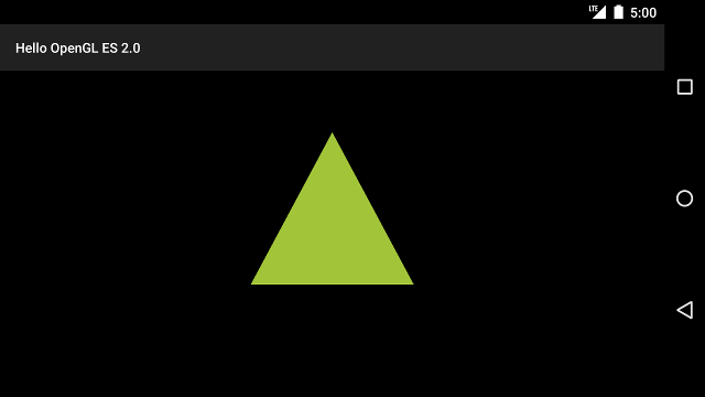
চিত্র 1. একটি অভিক্ষেপ এবং ক্যামেরা ভিউ প্রয়োগ করে আঁকা ত্রিভুজ।
এখন আপনার কাছে একটি অ্যাপ্লিকেশন রয়েছে যা আপনার আকারগুলি সঠিক অনুপাতে প্রদর্শন করে, এটি আপনার আকারগুলিতে গতি যুক্ত করার সময়।
এই পৃষ্ঠার কন্টেন্ট ও কোডের নমুনাগুলি Content License-এ বর্ণিত লাইসেন্সের অধীনস্থ। Java এবং OpenJDK হল Oracle এবং/অথবা তার অ্যাফিলিয়েট সংস্থার রেজিস্টার্ড ট্রেডমার্ক।
2025-07-29 UTC-তে শেষবার আপডেট করা হয়েছে।
[[["সহজে বোঝা যায়","easyToUnderstand","thumb-up"],["আমার সমস্যার সমাধান হয়েছে","solvedMyProblem","thumb-up"],["অন্যান্য","otherUp","thumb-up"]],[["এতে আমার প্রয়োজনীয় তথ্য নেই","missingTheInformationINeed","thumb-down"],["খুব জটিল / অনেক ধাপ","tooComplicatedTooManySteps","thumb-down"],["পুরনো","outOfDate","thumb-down"],["অনুবাদ সংক্রান্ত সমস্যা","translationIssue","thumb-down"],["নমুনা / কোড সংক্রান্ত সমস্যা","samplesCodeIssue","thumb-down"],["অন্যান্য","otherDown","thumb-down"]],["2025-07-29 UTC-তে শেষবার আপডেট করা হয়েছে।"],[],[],null,["# Apply projection and camera views\n\nIn the OpenGL ES environment, projection and camera views allow you to display drawn objects in a\nway that more closely resembles how you see physical objects with your eyes. This simulation of\nphysical viewing is done with mathematical transformations of drawn object coordinates:\n\n- *Projection* - This transformation adjusts the coordinates of drawn objects based on the width and height of the [GLSurfaceView](/reference/android/opengl/GLSurfaceView) where they are displayed. Without this calculation, objects drawn by OpenGL ES are skewed by the unequal proportions of the view window. A projection transformation typically only has to be calculated when the proportions of the OpenGL view are established or changed in the [onSurfaceChanged()](/reference/android/opengl/GLSurfaceView.Renderer#onSurfaceChanged(javax.microedition.khronos.opengles.GL10, int, int)) method of your renderer. For more information about OpenGL ES projections and coordinate mapping, see [Mapping coordinates for drawn\n objects](/develop/ui/views/graphics/opengl/about-opengl#coordinate-mapping).\n- *Camera View* - This transformation adjusts the coordinates of drawn objects based on a virtual camera position. It's important to note that OpenGL ES does not define an actual camera object, but instead provides utility methods that simulate a camera by transforming the display of drawn objects. A camera view transformation might be calculated only once when you establish your [GLSurfaceView](/reference/android/opengl/GLSurfaceView), or might change dynamically based on user actions or your application's function.\n\nThis lesson describes how to create a projection and camera view and apply it to shapes drawn in\nyour [GLSurfaceView](/reference/android/opengl/GLSurfaceView).\n\nDefine a projection\n-------------------\n\nThe data for a projection transformation is calculated in the [onSurfaceChanged()](/reference/android/opengl/GLSurfaceView.Renderer#onSurfaceChanged(javax.microedition.khronos.opengles.GL10, int, int))\nmethod of your [GLSurfaceView.Renderer](/reference/android/opengl/GLSurfaceView.Renderer) class. The following example code\ntakes the height and width of the [GLSurfaceView](/reference/android/opengl/GLSurfaceView) and uses it to populate a\nprojection transformation [Matrix](/reference/android/opengl/Matrix) using the [Matrix.frustumM()](/reference/android/opengl/Matrix#frustumM(float[], int, float, float, float, float, float, float)) method: \n\n### Kotlin\n\n```kotlin\n// vPMatrix is an abbreviation for \"Model View Projection Matrix\"\nprivate val vPMatrix = FloatArray(16)\nprivate val projectionMatrix = FloatArray(16)\nprivate val viewMatrix = FloatArray(16)\n\noverride fun onSurfaceChanged(unused: GL10, width: Int, height: Int) {\n GLES20.glViewport(0, 0, width, height)\n\n val ratio: Float = width.toFloat() / height.toFloat()\n\n // this projection matrix is applied to object coordinates\n // in the onDrawFrame() method\n Matrix.frustumM(projectionMatrix, 0, -ratio, ratio, -1f, 1f, 3f, 7f)\n}\n```\n\n### Java\n\n```java\n// vPMatrix is an abbreviation for \"Model View Projection Matrix\"\nprivate final float[] vPMatrix = new float[16];\nprivate final float[] projectionMatrix = new float[16];\nprivate final float[] viewMatrix = new float[16];\n\n@Override\npublic void onSurfaceChanged(GL10 unused, int width, int height) {\n GLES20.glViewport(0, 0, width, height);\n\n float ratio = (float) width / height;\n\n // this projection matrix is applied to object coordinates\n // in the onDrawFrame() method\n Matrix.frustumM(projectionMatrix, 0, -ratio, ratio, -1, 1, 3, 7);\n}\n```\n\nThis code populates a projection matrix, `mProjectionMatrix` which you can then combine\nwith a camera view transformation in the [onDrawFrame()](/reference/android/opengl/GLSurfaceView.Renderer#onDrawFrame(javax.microedition.khronos.opengles.GL10)) method, which is shown in the next section.\n\n**Note:** Just applying a projection transformation to your\ndrawing objects typically results in a very empty display. In general, you must also apply a camera\nview transformation in order for anything to show up on screen.\n\nDefine a camera view\n--------------------\n\nComplete the process of transforming your drawn objects by adding a camera view transformation as\npart of the drawing process in your renderer. In the following example code, the camera view\ntransformation is calculated using the [Matrix.setLookAtM()](/reference/android/opengl/Matrix#setLookAtM(float[], int, float, float, float, float, float, float, float, float, float))\nmethod and then combined with the previously calculated projection matrix. The combined\ntransformation matrices are then passed to the drawn shape. \n\n### Kotlin\n\n```kotlin\noverride fun onDrawFrame(unused: GL10) {\n ...\n // Set the camera position (View matrix)\n Matrix.setLookAtM(viewMatrix, 0, 0f, 0f, 3f, 0f, 0f, 0f, 0f, 1.0f, 0.0f)\n\n // Calculate the projection and view transformation\n Matrix.multiplyMM(vPMatrix, 0, projectionMatrix, 0, viewMatrix, 0)\n\n // Draw shape\n triangle.draw(vPMatrix)\n```\n\n### Java\n\n```java\n@Override\npublic void onDrawFrame(GL10 unused) {\n ...\n // Set the camera position (View matrix)\n Matrix.setLookAtM(viewMatrix, 0, 0, 0, 3, 0f, 0f, 0f, 0f, 1.0f, 0.0f);\n\n // Calculate the projection and view transformation\n Matrix.multiplyMM(vPMatrix, 0, projectionMatrix, 0, viewMatrix, 0);\n\n // Draw shape\n triangle.draw(vPMatrix);\n}\n```\n\nApply projection and camera transformations\n-------------------------------------------\n\nIn order to use the combined projection and camera view transformation matrix shown in the\npreviews sections, first add a matrix variable to the *vertex shader* previously defined\nin the `Triangle` class: \n\n### Kotlin\n\n```kotlin\nclass Triangle {\n\n private val vertexShaderCode =\n // This matrix member variable provides a hook to manipulate\n // the coordinates of the objects that use this vertex shader\n \"uniform mat4 uMVPMatrix;\" +\n \"attribute vec4 vPosition;\" +\n \"void main() {\" +\n // the matrix must be included as a modifier of gl_Position\n // Note that the uMVPMatrix factor *must be first* in order\n // for the matrix multiplication product to be correct.\n \" gl_Position = uMVPMatrix * vPosition;\" +\n \"}\"\n\n // Use to access and set the view transformation\n private var vPMatrixHandle: Int = 0\n\n ...\n}\n```\n\n### Java\n\n```java\npublic class Triangle {\n\n private final String vertexShaderCode =\n // This matrix member variable provides a hook to manipulate\n // the coordinates of the objects that use this vertex shader\n \"uniform mat4 uMVPMatrix;\" +\n \"attribute vec4 vPosition;\" +\n \"void main() {\" +\n // the matrix must be included as a modifier of gl_Position\n // Note that the uMVPMatrix factor *must be first* in order\n // for the matrix multiplication product to be correct.\n \" gl_Position = uMVPMatrix * vPosition;\" +\n \"}\";\n\n // Use to access and set the view transformation\n private int vPMatrixHandle;\n\n ...\n}\n```\n\nNext, modify the `draw()` method of your graphic objects to accept the combined\ntransformation matrix and apply it to the shape: \n\n### Kotlin\n\n```kotlin\nfun draw(mvpMatrix: FloatArray) { // pass in the calculated transformation matrix\n ...\n\n // get handle to shape's transformation matrix\n vPMatrixHandle = GLES20.glGetUniformLocation(mProgram, \"uMVPMatrix\")\n\n // Pass the projection and view transformation to the shader\n GLES20.glUniformMatrix4fv(vPMatrixHandle, 1, false, mvpMatrix, 0)\n\n // Draw the triangle\n GLES20.glDrawArrays(GLES20.GL_TRIANGLES, 0, vertexCount)\n\n // Disable vertex array\n GLES20.glDisableVertexAttribArray(positionHandle)\n}\n```\n\n### Java\n\n```java\npublic void draw(float[] mvpMatrix) { // pass in the calculated transformation matrix\n ...\n\n // get handle to shape's transformation matrix\n vPMatrixHandle = GLES20.glGetUniformLocation(mProgram, \"uMVPMatrix\");\n\n // Pass the projection and view transformation to the shader\n GLES20.glUniformMatrix4fv(vPMatrixHandle, 1, false, mvpMatrix, 0);\n\n // Draw the triangle\n GLES20.glDrawArrays(GLES20.GL_TRIANGLES, 0, vertexCount);\n\n // Disable vertex array\n GLES20.glDisableVertexAttribArray(positionHandle);\n}\n```\n\nOnce you have correctly calculated and applied the projection and camera view transformations,\nyour graphic objects are drawn in correct proportions and should look like this:\n\n\n**Figure 1.** Triangle drawn with a projection and camera view applied.\n\nNow that you have an application that displays your shapes in correct proportions, it's time to\nadd motion to your shapes."]]