
In Compose, you can chain multiple modifiers together to change the look and feel of a composable. These modifier chains can affect the constraints passed to composables, which define width and height bounds.
This page describes how chained modifiers affect constraints and, in turn, the measurement and placement of composables.
Modifiers in the UI tree
To understand how modifiers influence each other, it's helpful to visualize how they appear in the UI tree, which is generated during the composition phase. For more information, see the Composition section.
In the UI tree, you can visualize modifiers as wrapper nodes for the layout nodes:
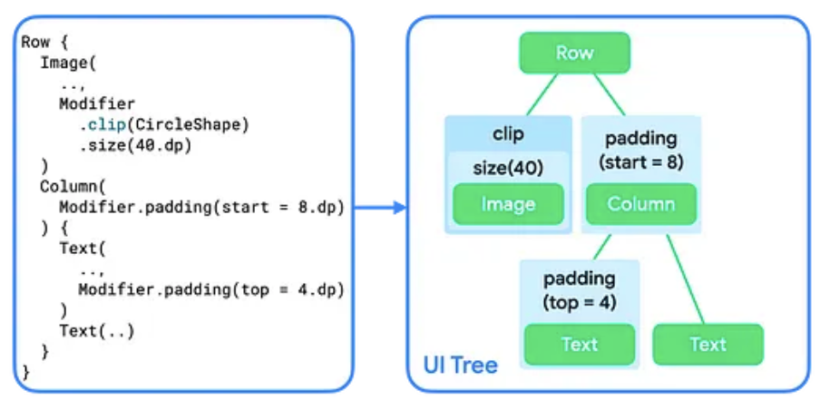
Adding more than one modifier to a composable creates a chain of modifiers. When
you chain multiple modifiers, each modifier node wraps the rest of the chain
and the layout node within. For example, when you chain a clip and a
size modifier, the clip modifier node wraps the size modifier node,
which then wraps the Image layout node.
In the layout phase, the algorithm that walks the tree stays the same, but each modifier node is visited as well. This way, a modifier can change the size requirements and placement of the modifier or layout node that it wraps.
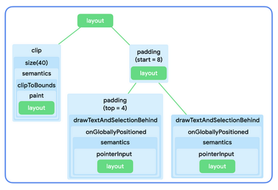
As shown in Figure 2, the implementation of the Image and Text composables
themselves consist of a chain of modifiers wrapping a single layout node. The
implementations of Row and Column are simply layout nodes that describe how
to lay out their children.
To summarize:
- Modifiers wrap a single modifier or layout node.
- Layout nodes can lay out multiple child nodes.
The following sections describe how to use this mental model to reason about modifier chaining and how it influences the size of composables.
Constraints in the layout phase
The layout phase follows a three-step algorithm to find each layout node's width, height, and x, y coordinate:
- Measure children: A node measures its children, if any.
- Decide own size: Based on those measurements, a node decides on its own size.
- Place children: Each child node is placed relative to a node's own position.
Constraints help find the right sizes for the nodes during the first two
steps of the algorithm. Constraints define the minimum and maximum bounds for a
node's width and height. When the node decides on its size, its measured size
should fall within this size range.
Types of constraints
A constraint can be one of the following:
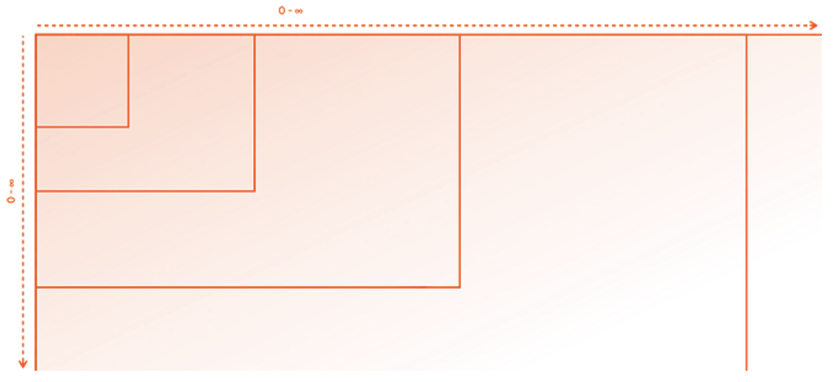
- Bounded: The node has a maximum and minimum width and height.
- Unbounded: The node is not constrained to any size. The maximum width and height bounds are set to infinity.
- Exact: The node is asked to follow an exact size requirement. The minimum and maximum bounds are set to the same value.
- Combination: The node follows a combination of the above constraint types. For example, a constraint could bound the width while allowing for an unbounded maximum height, or set an exact width but provide a bounded height.
The next section describes how these constraints are passed from a parent to a child.
How constraints are passed from parent to child
During the first step of the algorithm described in Constraints in the layout phase, constraints are passed down from parent to child in the UI tree.
When a parent node measures its children, it provides these constraints to each child to let them know how big or small they're allowed to be. Then, when it decides its own size, it also adheres to the constraints that were passed in by its own parents.
At a high level, the algorithm works in the following way:
- To decide the size it actually wants to occupy, the root node in the UI tree measures its children and forwards the same constraints to its first child.
- If the child is a modifier that does not impact measurement, it forwards the constraints to the next modifier. The constraints are passed down the modifier chain as-is unless a modifier that impacts measurement is reached. The constraints are then re-sized accordingly.
- Once a node is reached that doesn't have any children (referred to as a "leaf node"), it decides its size based on the constraints that were passed in, and returns this resolved size to its parent.
- The parent adapts its constraints based on this child's measurements, and calls its next child with these adjusted constraints.
- Once all children of a parent are measured, the parent node decides on its own size and communicates that to its own parent.
- This way, the whole tree is traversed depth-first. Eventually, all the nodes have decided on their sizes, and the measurement step is completed.
For an in-depth example, see the Constraints and modifier order video.
Modifiers that affect constraints
You learned in the previous section that some modifiers can affect constraint size. The following sections describe specific modifiers that impact constraints.
size modifier
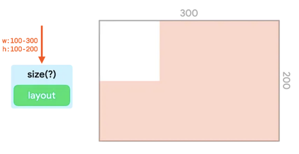
The size modifier declares the preferred size of the content.
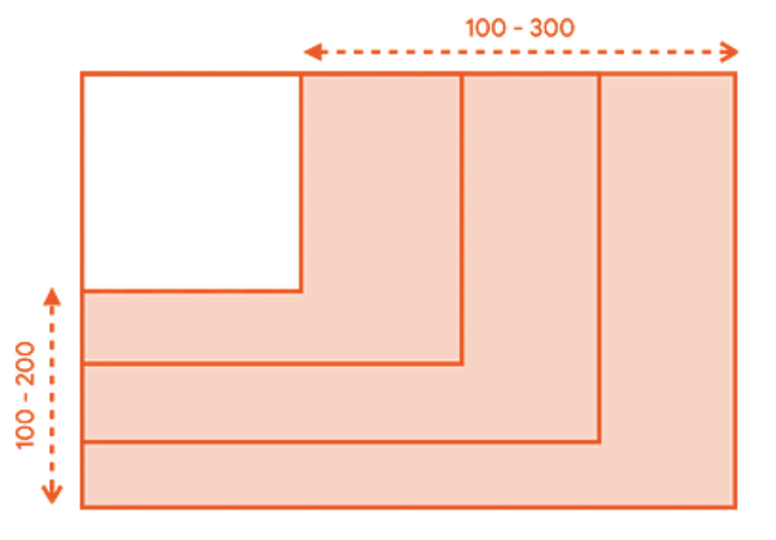
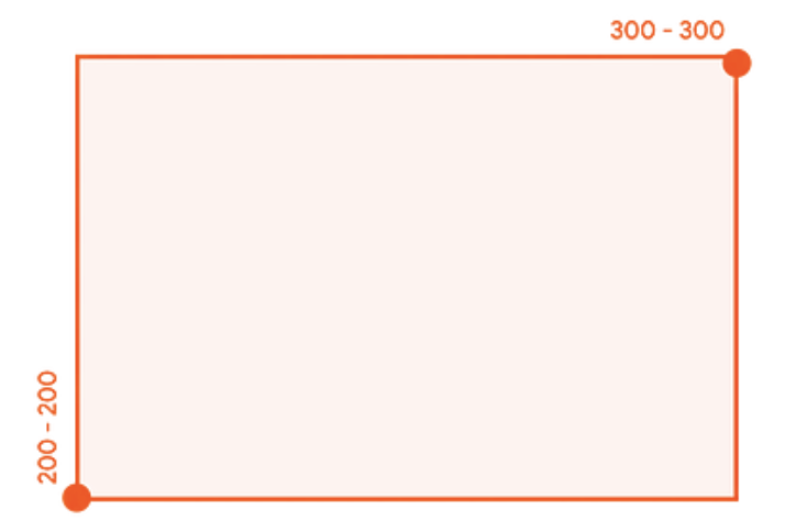
For example, the following UI tree should be rendered in a container of 300dp
by 200dp. The constraints are bounded, allowing widths between 100dp and
300dp, and heights between 100dp and 200dp:
The size modifier adapts incoming constraints to match the value passed to it.
In this example, the value is 150dp:
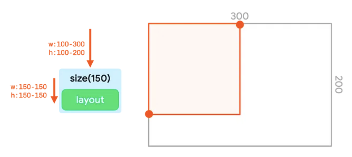
size modifier adjusting constraints to 150dp.If the width and height are smaller than the smallest constraint bound, or larger than the largest constraint bound, the modifier matches the passed constraints as closely as it can while still adhering to the constraints passed in:
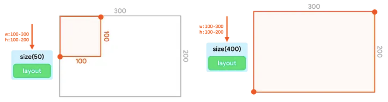
size modifier adhering to the passed constraint as closely
as possible.Note that chaining multiple size modifiers does not work. The first size
modifier sets both the minimum and maximum constraints to a fixed value. Even if
the second size modifier requests a smaller or larger size, it still needs to
adhere to the exact bounds passed in, so it won't override those values:
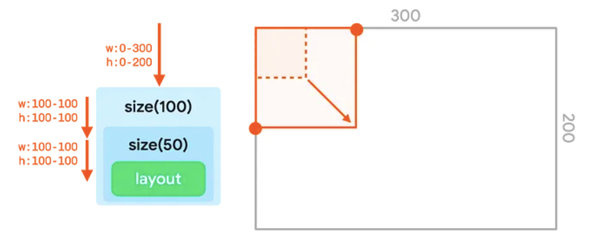
size modifiers, in which the second value passed
in (50dp) does not override the first value (100dp).requiredSize modifier
Use the requiredSize modifier instead of size if you need your
node to override the incoming constraints. The requiredSize modifier replaces
the incoming constraints and passes the size you specify as exact bounds.
When the size is passed back up the tree, the child node will be centered in the available space:
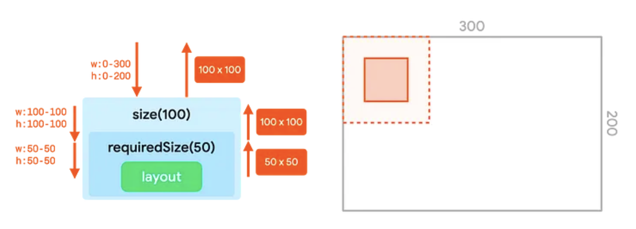
requiredSize modifier overriding incoming constraints from
the size modifier.width and height modifiers
The size modifier adapts both the width and height of the constraints. With
the width modifier, you can set a fixed width but leave the height undecided.
Similarly, with the height modifier, you can set a fixed height, but leave the
width undecided:
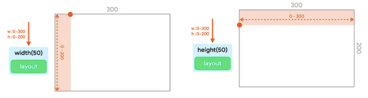
width modifier and height modifier setting a fixed width
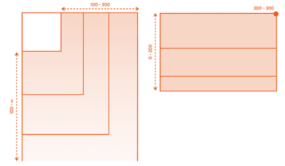
and height, respectively.sizeIn modifier
The sizeIn modifier lets you set exact minimum and maximum constraints
for width and height. Use the sizeIn modifier if you need fine-grained control
over the constraints.
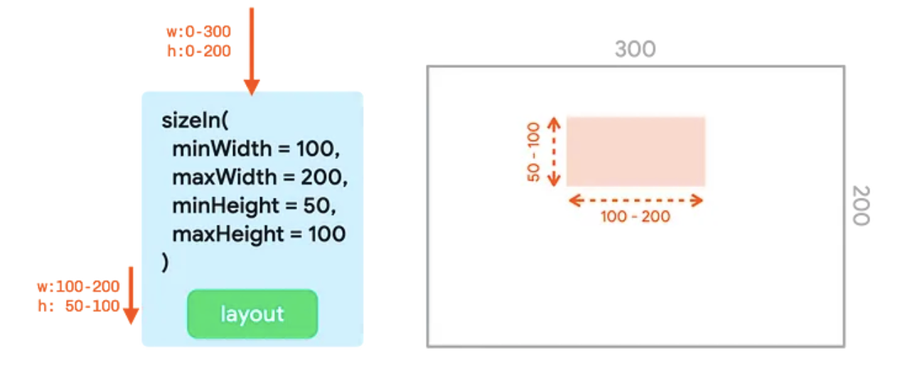
sizeIn modifier with minWidth, maxWidth, minHeight, and
maxHeight set.Examples
This section shows and explains the output from several code snippets with chained modifiers.
Image( painterResource(R.drawable.hero), contentDescription = null, Modifier .fillMaxSize() .size(50.dp) )
This snippet produces the following output:
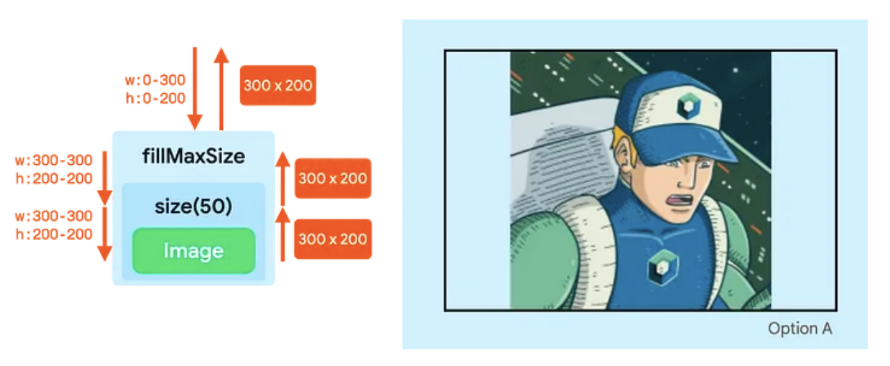
- The
fillMaxSizemodifier changes the constraints to set both the minimum width and height to the maximum value —300dpin width and200dpin height. - Even though the
sizemodifier wants to use a size of50dp, it still needs to adhere to the incoming minimum constraints. So thesizemodifier will also output the exact constraint bounds of300by200, effectively ignoring the value provided in thesizemodifier. - The
Imagefollows these bounds and reports a size of300by200, which is passed all the way up the tree.
Image( painterResource(R.drawable.hero), contentDescription = null, Modifier .fillMaxSize() .wrapContentSize() .size(50.dp) )
This snippet produces the following output:
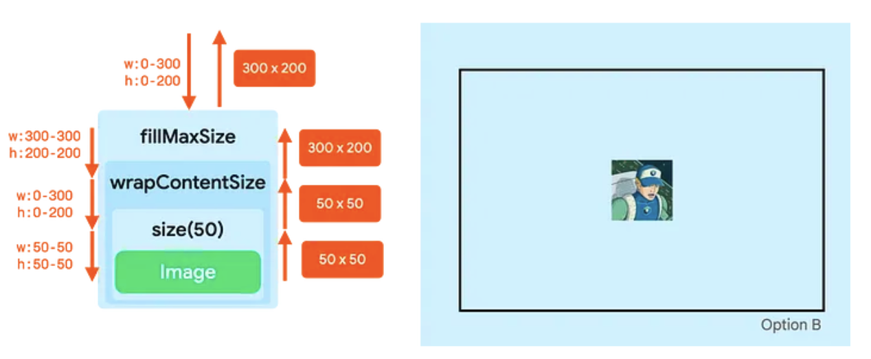
- The
fillMaxSizemodifier adapts the constraints to set both the minimum width and height to the maximum value —300dpin width, and200dpin height. - The
wrapContentSizemodifier resets the minimum constraints. So, whilefillMaxSizeresulted in fixed constraints,wrapContentSizeresets it back to bounded constraints. The following node can now take up the whole space again, or be smaller than the entire space. - The
sizemodifier sets the constraints to minimum and maximum bounds of50. - The
Imageresolves to a size of50by50, and thesizemodifier forwards that. - The
wrapContentSizemodifier has a special property. It takes its child and puts it in the center of the available minimum bounds that were passed to it. The size it communicates to its parents is thus equal to the minimum bounds that were passed into it.
By combining just three modifiers, you can define a size for the composable and center it in its parent.
Image( painterResource(R.drawable.hero), contentDescription = null, Modifier .clip(CircleShape) .padding(10.dp) .size(100.dp) )
This snippet produces the following output:
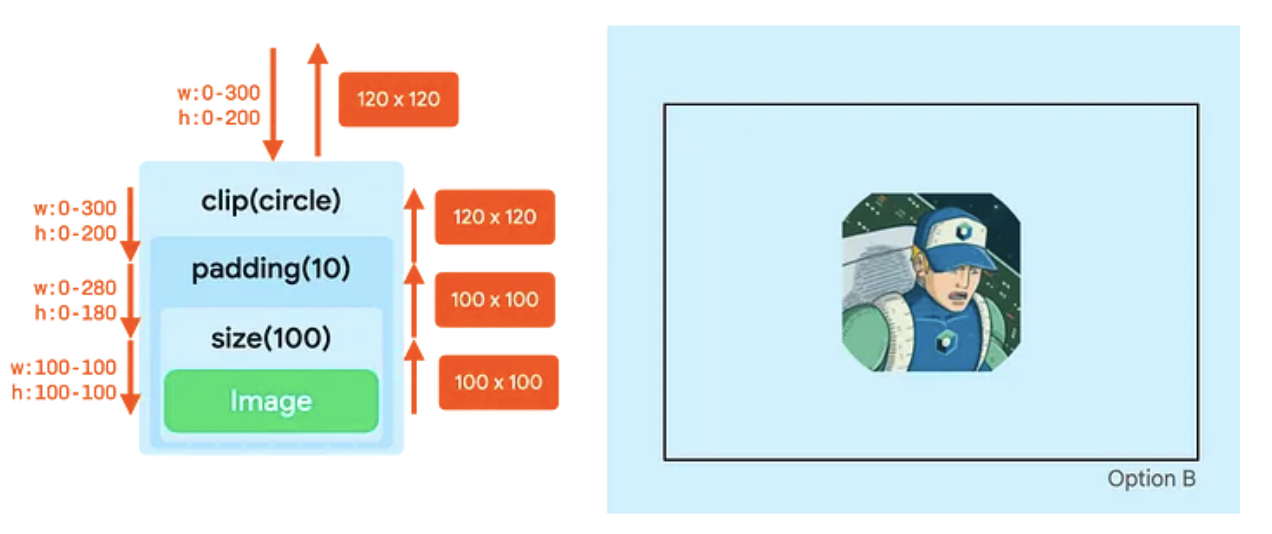
- The
clipmodifier does not change the constraints.- The
paddingmodifier lowers the maximum constraints. - The
sizemodifier sets all constraints to100dp. - The
Imageadheres to those constraints and reports a size of100by100dp. - The
paddingmodifier adds10dpon all sizes, so it increases the reported width and height by20dp. - Now in the drawing phase, the
clipmodifier acts on a canvas of120by120dp. So, it creates a circle mask of that size. - The
paddingmodifier then insets its content by10dpon all sizes, so it lowers the canvas size to100by100dp. - The
Imageis drawn in that canvas. The image is clipped based on the original circle of120dp, so the output is a non-round result.
- The