
Introduction
This document defines the behavior of a new file format that encodes a logarithmic range gain map image in a JPEG image file. Legacy readers that don't support the new format read and display the conventional low dynamic range image from the image file. Readers that support the format combine the primary image with the gain map and render a high dynamic range image on compatible displays.
The remainder of this document describes the methods of the processes needed to make use of this format. At a high level, the life cycle of an image conforming to this format is:
Encoding
- Gain map generation
- Gain map compression
- Gain map container generation
Decoding
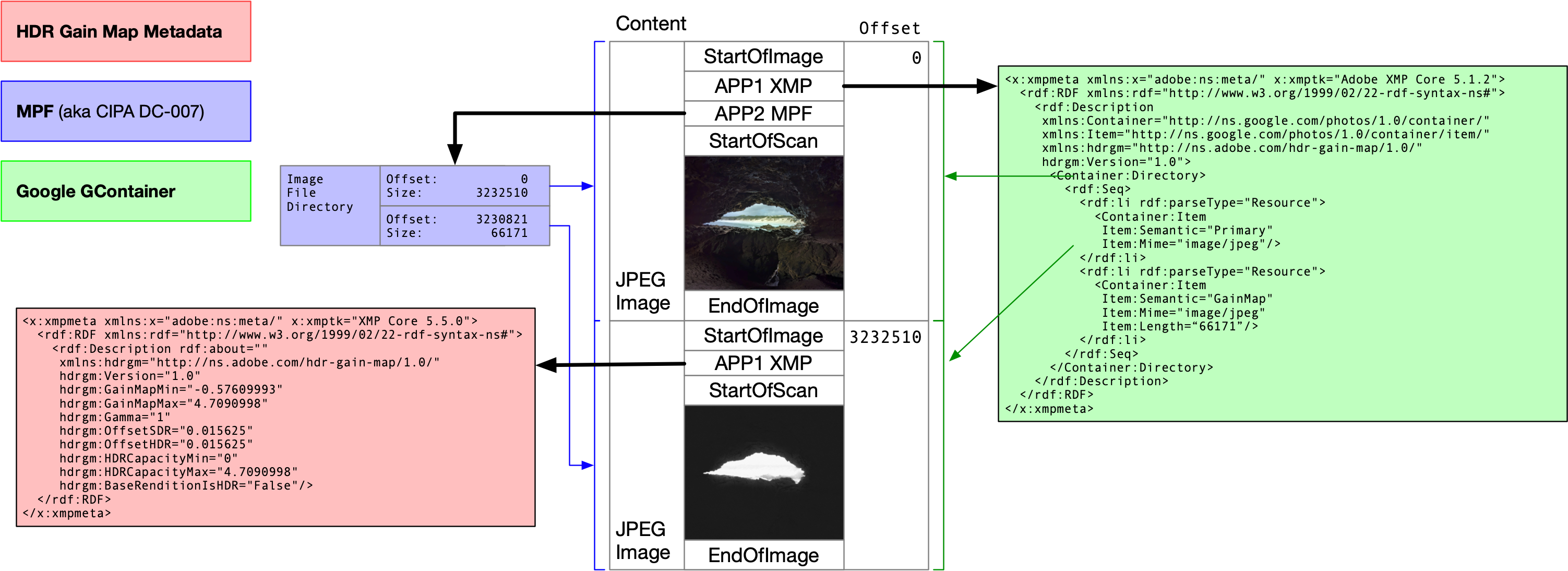
Figure 1. Example file layout and relevant metadata.
Motivation
The goal of this file format is to encode additional information in SDR image files that can be used in combination with the display technique to produce their optimal HDR renditions, in a single file.
For this to be practical, the file format must:
- Be backward compatible, so that on naive viewers, the conventional SDR image is displayed.
- Not take up too much extra space.
Additionally, the display technique must:
- Not require heavy processing to decode.
- Be able to adapt to any ratio between a display's HDR and SDR white points, which can vary significantly between devices, or even temporally on a single device.
And finally, the technique must be able to do all of the preceding actions without ever:
- Clipping highlights.
- Crushing shadows.
- Changing or compressing local contrast.
- Changing relative tonal relationships (between objects in the scene).
Dependencies
The following are normative references for this specification:
- Adobe XMP Specification Part 3: Storage in Files
- ISO 16684-1:2019 XMP Specification Part 1
- ISO/IEC 14496-12 ISO base media file format
- T.81 (09/92) Digital compression and coding of continuous-tone still images
- White Paper of CIPA DC-x 007-2009 Multi-Picture Format
Definitions
SDR display
- A conventional display, not designed for displaying HDR content. These displays typically produce a nominal peak brightness of about 400 cd/m2 or less.
HDR display
- A display designed for HDR content. These displays typically produce a nominal peak brightness greater than that of an SDR Display, typically 800 cd/m2 or greater, and typically also have better contrast ratios than SDR displays.
Primary image
- The first instance of an image in a GContainer file with secondary media files appended to it. The primary image contains GContainer XMP metadata defining the order and properties of subsequent secondary media item files in the file container.
Secondary image
- Subsequent media item files that are appended to the primary image in a GContainer file.
Range compression
- In photography, real-world scenes often have more dynamic range than an SDR display can represent. Operations such as Range compression, also called local tone mapping, are needed to reduce the dynamic range of an image. This reduction needs to avoid clipping highlights or crushing shadows, while preserving local contrast as much as possible. You try to reduce the size of large luminance edges in the image, which contribute more to its global contrast, while trying to preserve the size of the small luminance edges, which are the details. Although there are many different implementations, such an operation is standard on most modern digital cameras today.
SDR white point
- The maximum linear luminance of SDR content on a display at a certain point in time.
HDR white point
- The maximum linear luminance of HDR content on a display at a certain point in time. This value is typically higher than the SDR white point.
Boost
- The HDR white point divided by the SDR white point.
Max content boost (
max_content_boostin equations)- This value lets the content creator constrain how much brighter an image can get, when shown on an HDR display, relative to the SDR rendition.
- This value is a constant for a particular image. For example, if the value is four, then for any given pixel, the linear luminance of the displayed HDR rendition must be, at the most, 4x the linear luminance of the SDR rendition. In practice, this means that the brighter parts of the scene can be shown up to 4x brighter.
- In practice, this value is typically greater than 1.0.
- Always greater than or equal to Min content boost.
Min content boost (
min_content_boostin equations)- This value lets the content creator constrain how much darker an image can get, when shown on an HDR display, relative to the SDR rendition. This value is a constant for a particular image.
- If, for example, the value is 0.5, then for any given pixel, the linear luminance of the displayed HDR rendition must be (at the least) 0.5x the linear luminance of the SDR rendition.
- In practice, this value is typically equal to or just less than 1.0.
- Always less than or equal to Max content boost.
Max display boost (
max_display_boostin equations)- The maximum available boost supported by a display, at a given point in time. This value can change over time based on device settings and other factors, such as ambient light conditions, or how many bright pixels are on the screen.
- For example, if this value is 4.0, then the display is capable of displaying a pixel that is at most four times brighter than the SDR white point. This value is always >= 1.0, since the display can always display HDR white at least as bright as SDR white.
Display boost
- Equal to the lesser of max content boost and max display boost. This value is always >= 1.0.
- For example, if max content boost is 4.0 and max display boost is 3.0, then display boost is 3.0. Pixels are displayed as much as 3x brighter than SDR, since the display capabilities are the limiting factor.
- For another example, if max content boost is 4.0 and max display boost is 5.0, then display boost is 4.0. Pixels are displayed as much as 4x brighter than SDR, since the content's intent is the limiting factor.
Target HDR rendition
- The ideal HDR rendition, according to the content creator.
Adapted HDR rendition
- The final HDR rendition that is shown on the display, after adapting the Target HDR rendition for the current display boost.
Gain map (
recovery(x, y)in equations)- A map indicating how much to brighten each pixel, in the SDR rendition, to produce the target HDR rendition. This map can be single-channel or multi-channel. A multi-channel map indicates a separate gain for each color channel, such as red, green, and blue. This document illustrates the case of a single-channel map.
clamp(x, a, b)- Clamp the value x to the range [a, b].
exp2(x)- Base 2 exponentiation; 2x.
floor(x)- Returns the nearest integer equal to or less than x.
log2(x)- Base 2 logarithm; log2(x)
pow(b, x)- Exponentiation; bx.
XMP
- Extensible Metadata Platform. A standard that defines a method for encoding metadata into an image container; defined by ISO 16684-1:2011(E) XMP Specification Part 1.
Multi-Picture Format
- Multi-Picture Format is a technique developed by the Camera and Imaging Products Association (CIPA) for storing multiple JPEG encoded images in a single JPEG file.
- For more information, see the related dependency, White Paper of CIPA DC-x 007-2009 Multi-Picture Format.
GContainer
- GContainer is a method for storing multiple images in one image container, where one image is considered to be the primary image. Any additional images are considered alternative versions or auxiliary. XMP metadata is used to communicate the presence and meaning of any additional images. For more information, see the GContainer details section.
Encode
This section describes how to encode a conforming JPEG file. Refer to T.81 (09/92) Digital compression and coding of continuous-tone still images, in the Dependencies section, for more information about the JPEG format.
Gain map generation
Camera imaging pipelines commonly perform a range compression operation to compress higher dynamic range luminance data to the lower range of conventional SDR displays. The gain map provides a mechanism to store data sufficient to recover the original, higher dynamic range luminance data.
The following calculations in this section assume floating point arithmetic.
The following functions describe the SDR image:
SDR'(x, y)is the three-channel, non-linear (typically gamma-encoded) primary image.SDR(x, y)is the linear version of the three-channel primary image, obtained by transforming to a linear version of the primary image color space. For example, from a color space with a sRGB transfer function to a linear color space that preserves sRGB color primaries.
The Ysdr(x, y) function is defined on the range of 0.0 to 1.0 and is the
standard dynamic range primary image linear luminance:
Ysdr(x, y) = primary_color_profile_to_luminance(SDR(x, y))
Similar definitions exist for the HDR image.
HDR'(x, y)is the three-channel non-linear, that is, a PQ or HLG encoded image.HDR(x, y)is the three-channel linear HDR image.
Yhdr(x, y) is the luminance at a given point of the HDR image:
Yhdr(x, y) = primary_color_profile_to_luminance(HDR(x, y))
Yhdr(x, y) is defined in the range 0.0 to max content boost.
The SDR and HDR images must be the same resolution. The color profile of the SDR image defines the color space of the HDR image.
For example, if the SDR primary image has a Display-P3 color profile, then the HDR image is defined relative to the primary colors of that profile. This means the HDR image also has Display-P3 primaries.
The gain map is computed from two linear images containing the wanted HDR image
luminance, Yhdr(x, y), and the standard range luminance image, Ysdr(x, y).
The pixel_gain(x, y) function is defined as the ratio between the Yhdr(x, y)
function and the Ysdr(x, y) function:
pixel_gain(x, y) = (Yhdr(x, y) + offset_hdr) / (Ysdr(x, y) + offset_sdr)
The pixel_gain(x, y) function behavior where Ysdr(x, y) and offset_sdr are
both zero is implementation-defined.
For example, implementations can handle the case where Ysdr(x, y) and
offset_sdr are both zero by defining pixel_gain(x, y) as 1.0. Alternatively,
implementations also avoid this scenario by utilizing a non-zero offset_sdr.
The implementation might choose the values of offset_sdr and offset_hdr.
The gain map is a scalar function that encodes pixel_gain(x, y) in a
logarithmic space, relative to max content boost and min content boost:
map_min_log2 = log2(min_content_boost)
map_max_log2 = log2(max_content_boost)

log_recovery(x, y) = (log2(pixel_gain(x, y)) - map_min_log2)
                   / (map_max_log2 - map_min_log2)
clamped_recovery(x, y) = clamp(log_recovery(x, y), 0.0, 1.0)
recovery(x, y) = pow(clamped_recovery(x, y), map_gamma)
The recovery(x, y) function behavior where pixel_gain(x, y) is zero is
implementation defined, because log2(0) is undefined.
map_gamma is a floating point number that must be greater than 0.0 and is
chosen by the implementation.
The values of max content boost and min content boost are implementation-defined, and can be arbitrarily decided by the content creator. Max content boost must be greater than or equal to 1.0. Min content boost must be in the range (0.0, 1.0].
Values in recovery(x, y) are limited to the range [0.0, 1.0].
The gain map is stored in a secondary image JPEG, and therefore must be encoded
using 8-bit, unsigned integer values, thus in the range [0, 255]. Each value
represents a recovery(x, y) value and is stored in one pixel of the secondary
image.
For 8-bit unsigned integer storage, the encoded value is defined as the following:
encoded_recovery(x, y) = floor(recovery(x, y) * 255.0 + 0.5)
Calculation of the encode function is done in floating point and converted at the end to the 8-bit unsigned integer result by rounding as indicated.
This encoding results in an 8-bit unsigned integer representation of
recovery(x, y) values, from 0.0 to 1.0. The encoded gain map must be stored in
a secondary image item as a JPEG. The implementation chooses the amount of
compression to use during JPEG encoding.
After the gain map is stored in a secondary image, it is appended to a primary image with MPF and GContainer XMP metadata. The primary image GContainer directory must contain an item for the gain map image.
The resolution of the stored gain map is implementation-defined and can be different from the resolution from the primary image. In the case that the Gain Map is scaled to a different resolution from the primary image for storage, the sampling method must be bilinear or better, and is implementation defined.
The orientation of the gain map must match that of the primary image. If present, any orientation metadata in the stored gain map image, as in EXIF, isn't used.
If present, the gain map's color profile isn't used.
Gain map container
Color profile
The color profile of the image must be indicated via an ICC Profile for the primary image.
XMP attributes
The primary image contains XMP metadata to define at least two images with extra semantic information for the HDR gain map format.
The following subsections contain details specific to this format. Additional information regarding general conformance to GContainer is specified in the GContainer details section.
Attribute values described in the following tables are stored as XMP simple values of the specified XMP basic value types.
Item semantic values
The Item:Semantic property defines the application-specific meaning
of each media item in the container directory.
| Value | Description |
|---|---|
| Primary | Indicates that the media item is the primary image, ready for display, in the container. The directory must contain one "Primary" item. |
| GainMap | Indicates that the media item is a gain map. The directory might contain at most one "GainMap" item. |
HDR Gain map metadata
Gain map metadata encodes information about how to interpret and apply the gain map to produce the HDR representation of the primary image.
The XMP namespace URI for the gain map metadata XMP extension is
http://ns.adobe.com/hdr-gain-map/1.0/. The default namespace prefix is
hdrgm.
This metadata is stored in the gain map image's XMP packet and the following
properties must appear in the gain map image XMP's rdf:Description:
| Name | Type | Description |
|---|---|---|
| hdrgm:Version | Text | The version of the gain map format in use. This version is "1.0". Required. |
| hdrgm:BaseRenditionIsHDR | Boolean | Indicates the dynamic range of the primary image. "False" indicates the primary image is SDR and the gain map can be combined with it to produce an HDR rendition. "True" indicates the primary image is HDR and the gain map might be combined with it to produce the SDR rendition. Must be "False". Optional; default value is "False". |
| hdrgm:GainMapMin | Real or ordered array of Reals | Stores the value(s) of map_min_log2. This is
log2 of min content boost, which is the minimum allowed ratio
of the linear luminance for the target HDR rendition relative to (divided
by) that of the SDR image, at a given pixel. May be a single Real, or an
ordered array of Reals. When an ordered array of Reals, it may contain one
item which applies to all channels or three items for the Red, Green, and
Blue channels respectively. Must be less than or equal to
hdrgm:GainMapMax. Optional; default value is 0.0. |
| hdrgm:GainMapMax | Real or ordered array of Reals | Stores the value(s) of map_max_log2. This is
log2 of max content boost, which is the maximum allowed ratio
of the linear luminance for the Target HDR rendition relative to (divided
by) that of the SDR image, at a given pixel. May be a single Real, or an
ordered array of Reals. When an ordered array of Reals, it may contain one
item which applies to all channels or three items for the Red, Green, and
Blue channels respectively. Must be greater than or equal to
hdrgm:GainMapMin. Required. |
| hdrgm:Gamma | Real or ordered array of Reals | Stores the value(s) of map_gamma. This is the gamma to
apply to the stored map values. May be a single Real, or an ordered array of
Reals. When an ordered array of Reals, it may contain one item which applies
to all channels or three items for the Red, Green, and Blue channels
respectively. Must be greater than 0.0. Optional; default value is
1.0. |
| hdrgm:OffsetSDR | Real or ordered array of Reals | Stores the value(s) of offset_sdr. This is the offset to
apply to the SDR pixel values during gain map generation and application.
May be a single Real, or an ordered array of Reals. When an ordered array of
Reals, it may contain one item which applies to all channels or three items
for the Red, Green, and Blue channels respectively. Must be 0.0 or greater.
Optional; default value is 0.015625 (1/64). |
| hdrgm:OffsetHDR | Real or ordered array of Reals | Stores the value(s) of offset_hdr. This is the offset to
apply to the HDR pixel values during gain map generation and application.
May be a single Real, or an ordered array of Reals. When an ordered array of
Reals, it may contain one item which applies to all channels or three items
for the Red, Green, and Blue channels respectively. Must be 0.0 or greater.
Optional; default value is 0.015625 (1/64). |
| hdrgm:HDRCapacityMin | Real | Stores the value of hdr_capacity_min. This is
log2 of the minimum display boost value for which the map is
applied at all. This value also affects how much to apply the gain map based
on the display boost. Must be 0.0 or greater. Optional; default
value is 0.0. |
| hdrgm:HDRCapacityMax | Real | Stores the value of hdr_capacity_max. This is
log2 of the maximum display boost value for which the map is
applied completely. This value also affects how much to apply the gain map
based on the display boost. Must be greater than
hdrgm:HDRCapacityMin. Required. |
Example gain map XMP
The following example of a valid gain map XMP packet contains metadata taken from the example file illustrated in the Introduction section.
<x:xmpmeta xmlns:x="adobe:ns:meta/" x:xmptk="XMP Core 5.5.0">
  <rdf:RDF xmlns:rdf="http://www.w3.org/1999/02/22-rdf-syntax-ns#">
    <rdf:Description rdf:about=""
     xmlns:hdrgm="http://ns.adobe.com/hdr-gain-map/1.0/"
     hdrgm:Version="1.0"
     hdrgm:GainMapMin="-0.57609993"
     hdrgm:GainMapMax="4.7090998"
     hdrgm:Gamma="1"
     hdrgm:OffsetSDR="0.015625"
     hdrgm:OffsetHDR="0.015625"
     hdrgm:HDRCapacityMin="0"
     hdrgm:HDRCapacityMax="4.7090998"
     hdrgm:BaseRenditionIsHDR="False"/>
  </rdf:RDF>
</x:xmpmeta>
MPF storage of the gain map
The gain map image must be stored as an additional image as defined in CIPA DC-x 007-2009 Multi-Picture Format, as referenced in the Dependencies section.
Decode
This section describes how to decode the gain map from a conforming JPEG file.
Signal of the format
A JPEG file conforming to this format may be identified by the presence of
hdrgm:Version="1.0" in the primary image's XMP packet, where hdrgm is the
namespace URI http://ns.adobe.com/hdr-gain-map/1.0/.
Locate the gain map image
For details on parsing and decoding the image, see the following GContainer
details section. A "GainMap" semantic item within the XMP
rdf:Directory is used to signal the location of a gain map image.
Alternatively, the MPF Index IFD and scanning images' XMP is used to determine
the location of a gain map.
Handle invalid metadata
Metadata is considered invalid if a required field is not present, or if any field is present with an invalid value. A value may be invalid because it is not parseable to the specified type or because it is outside of its expected range.
If invalid metadata is encountered, the gain map should be ignored and the SDR image should be displayed.
Display
Files encoded in the HDR gain map format might be rendered on either conventional SDR displays, or on HDR displays capable of higher-luminance output.
Use the gain map to create the adapted HDR rendition
The following calculations in this section assume floating-point arithmetic.
encoded_recovery(x, y) is the single-channel, 8-bit, unsigned integer value
from the gain map image.
If the gain map is a different resolution than the primary image, then
encoded_recovery(x, y) is instead determined by a filtered sampling of the
gain map image for x and y over the range of the primary image width and height,
respectively. The filtering method must be bilinear or better and is
implementation defined.
map_gamma is determined by the hdrgm:Gamma metadata field.
log_recovery(x, y) is the normalized floating point pixel gain in a
logarithmic space:
recovery(x, y) = encoded_recovery(x, y) / 255.0
log_recovery(x, y) = pow(recovery(x, y), 1.0 / map_gamma)
Max display boost is a scalar floating point value defined as the ratio between the current HDR white point and divided by the current SDR white point. This value is provided by the display system and can change over time.
hdr_capacity_max is determined by the hdrgm:HDRCapacityMax metadata field.
hdr_capacity_min is determined by the hdrgm:HDRCapacityMin metadata field.
weight_factor is determined as follows when hdrgm:BaseRenditionIsHDR is
"False":
unclamped_weight_factor = (log2(max_display_boost) - hdr_capacity_min)
                        / (hdr_capacity_max - hdr_capacity_min)
weight_factor = clamp(unclamped_weight_factor, 0.0, 1.0)
When hdrgm:BaseRenditionIsHDR is "True", the second equation is instead:
weight_factor = 1.0 - clamp(unclamped_weight_factor, 0.0, 1.0)
gain_map_max is determined by the hdrgm:GainMapMax metadata field.
gain_map_min is determined by the hdrgm:GainMapMin metadata field.
offset_sdr is determined by the hdrgm:OffsetSDR metadata field. offset_hdr
is determined by the hdrgm:OffsetHDR metadata field.
The linear adapted HDR rendition can be computed as follows:
log_boost(x, y) = gain_map_min * (1.0f - log_recovery(x, y))
                + gain_map_max * log_recovery(x, y)
HDR(x, y) = (SDR(x, y) + offset_sdr) * exp2(log_boost(x, y) * weight_factor)
          - offset_hdr
If needed, the implementation might apply a transform to HDR(x, y), to put the
data in the space expected by the display. Any such transformations must be
colorimetrically correct.
GContainer details
This section specifies additional requirements such that this format conforms with GContainer XML metadata. The metadata is serialized following ISO 166841:2011(E) XMP Specification Part 1 and embedded inside the primary image file as described in Adobe XMP Specification Part 3 Storage in Files. The primary image file contains the following items, formatted as RDF/XML.
XMP packet requirements
The XMP packet shall include the gain map metadata XMP extension via the
namespace URI http://ns.adobe.com/hdr-gain-map/1.0/. The default namespace
prefix is hdrgm.
The XMP packet shall define hdrgm:Version="1.0".
Container element
The XMP namespace for the GContainer XMP extension is
http://ns.google.com/photos/1.0/container/. The default namespace prefix is
Container.
The primary image contains a Container:Directory element in XMP metadata
defining the order and properties of the subsequent media file in the file
container. Each file in the container has a corresponding media item in the
Container:Directory. The media item describes the location in the file
container and the basic properties of each concatenated file.
The container element is encoded into the XMP metadata of the primary image and defines a directory of media items in the container. Media items must be located in the container file in the same order as the media item elements in the directory and must be tightly packed.
The directory can contain only one "Primary" image item and it must be the first item in the directory.
| Element name | Type | Description |
|---|---|---|
| Container:Directory | Ordered Array of Structures | Ordered array of structs each containing a Container:Item
struct defining the layout and contents of the container. |
Item element
Item elements describe how each media item is used by the application.
The XMP namespace URI for the GContainer Item XMP extension is
http://ns.google.com/photos/1.0/container/item/. The default namespace prefix
is Item.
The first media item must be the primary image. It must specify Item:Semantic
= "Primary" and an Item:Mime listed in
Item MIME type values.
The length of the primary image item is determined by parsing the primary image based on its MIME type starting at the beginning of the file container.
Media items can contain an Item:Padding attribute specifying additional
padding between the end of the media item and the beginning of the next media
item. When present on the last media item in the Container:Directory,
Item:Padding indicates padding between the end of the item and the end of the
file.
Each media item must contain Item:Mime type and Item:Semantic attributes.
The secondary image media items must contain Item:Length attributes.
Sequential media items can share resource data within the file container. The
first media item determines the location of the resource in the file container,
and subsequent shared media items have Item:Length set to 0. In the case that
the resource data is itself a container, Item:URI might be used to determine
the location of the media item data within the resource.
The location of media item resources in the container is determined by summing
the length of the primary image encoding, the Item:Length values of the
preceding secondary media item resources, and all preceding Item:Padding
values. Item:Padding is considered to be 0 on media item resources that don't
specify its value.
| Attribute name | Type | Description |
|---|---|---|
| Item:Mime | Text | Simple string indicating the MIME type of the media item in the container. For a definition, see the Item MIME type values section. Required. |
| Item:Semantic | Text | Simple string indicating the application specific meaning of the media item. For a definition, see the Item semantic values section. Required. |
| Item:Length | Integer | Simple string containing a positive integer length in bytes of the item. Length 0 indicates that the media item resource is shared with the previous media item. Required for secondary media items. Optional for the primary image media item. |
| Item:Label | Text | Implementation defined string used to disambiguate multiple item
elements with the same Item:Semantic. Optional. |
| Item:Padding | Integer | A string containing a positive integer length in bytes of additional
padding between the end of the media item and the beginning of the next
media item, or end of the file when used on the last media item in the
Container:Directory. A value of 0 is assumed when not present.
Optional. |
| Item:URI | Text | A URI string conforming to ISO/IEC 14496-12 section 8.11.9, containing the relative URI of the media data inside the media item resource. Default is the primary image resource. Optional for ISO base media file format ISO/IEC 14496-12 MIME types. May not be used otherwise. |
Item MIME type values
The Item:Mime attribute defines the MIME type of each media item
data.
| Value | Description |
|---|---|
| image/jpeg | JPEG image. |
Example GContainer XMP
The following example of a valid GContainer XMP packet has metadata taken from the example file illustrated in the Introduction section.
<x:xmpmeta xmlns:x="adobe:ns:meta/" x:xmptk="Adobe XMP Core 5.1.2">
  <rdf:RDF xmlns:rdf="http://www.w3.org/1999/02/22-rdf-syntax-ns#">
    <rdf:Description
     xmlns:Container="http://ns.google.com/photos/1.0/container/"
     xmlns:Item="http://ns.google.com/photos/1.0/container/item/"
     xmlns:hdrgm="http://ns.adobe.com/hdr-gain-map/1.0/"
     hdrgm:Version="1.0">
      <Container:Directory>
        <rdf:Seq>
          <rdf:li rdf:parseType="Resource">
            <Container:Item
             Item:Semantic="Primary"
             Item:Mime="image/jpeg"/>
          </rdf:li>
          <rdf:li rdf:parseType="Resource">
            <Container:Item
             Item:Semantic="GainMap"
             Item:Mime="image/jpeg"
             Item:Length="66171"/>
          </rdf:li>
        </rdf:Seq>
      </Container:Directory>
    </rdf:Description>
  </rdf:RDF>
</x:xmpmeta>
ISO 21496-1 Compatibility
ISO 21496-1 provides an alternative encapsulation mechanism for encoding gain map metadata in an image file. You can encode both Ultra HDR metadata and ISO 21496-1 metadata in one JPEG file using a single gainmap image in the file.
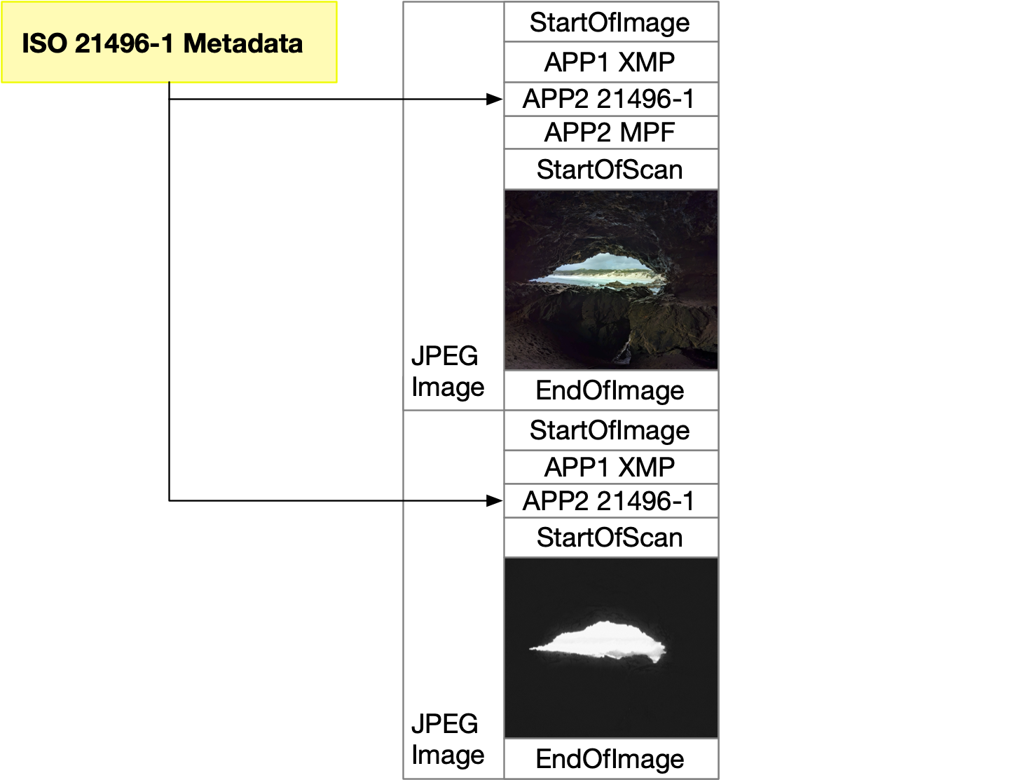
Figure 2. Example file layout with Ultra HDR and ISO 21496-1 metadata.
For maximum cross-platform compatibility, Android implementations and apps that implement their own encoding or decoding of JPEG files with gain maps should support encoding and decoding for both Ultra HDR v1 and ISO 21496-1 metadata. During an encode operation, the implementation or app should encode both metadata formats. If both types of metadata are present during a decode operation, the implementation or app should prefer using the ISO 21496-1 metadata.
Change Log
This section contains information about changes between versions of this specification.
v1.1
All changes in this version of the Ultra HDR specification are informational and about ISO 21496-1 compatibility. There are no changes to the actual file format.
- Add ISO 21496-1 Compatibility section.
v1.0
The initial Ultra HDR specification publication.